
1.4 TSI engine (EA111) · Cylinder head, valve gear · Chain drive
Checking timing chain
Special tools and workshop equipment required
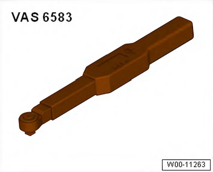
- Torque wrench - VAS 6583-
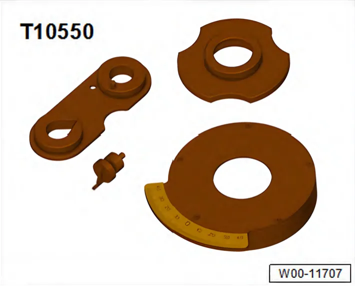
- Tester for checking elongation of chain links - T10550-
- Camshaft clamp - T10550/1-
- Indicator - T10550/2-
- Scale sleeve - T10550/3-
- The engine oil temperature must be at least 40°C ⇒ Vehicle diagnostic tester.
- The engine must necessarily not be at »TDC« position.
- Remove right front wheel ⇒ Running gear, axles, steering; Rep. gr. 44; Wheels, tyres.
- Remove noise insulation ⇒ Body, front; Rep. gr. 50; Noise insulation; Assembly overview - noise insulation.
- Remove front right wheel housing liner: ⇒ General body repairs, exterior; Rep. gr. 66; Removing and installing wheel housing liner.
- Remove poly V-belt ⇒ 13 – Crankshaft group.
- Drain coolant ⇒ 1.6 Draining and filling coolant (Polo).
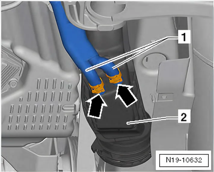
Vehicles with condensate trap on charge air pipe
- Open clamps -arrows-.
- Pull coolant hoses -1- off charge air pipe -2-, and clamp them off using hose clips up to 40 mm - 3093-.
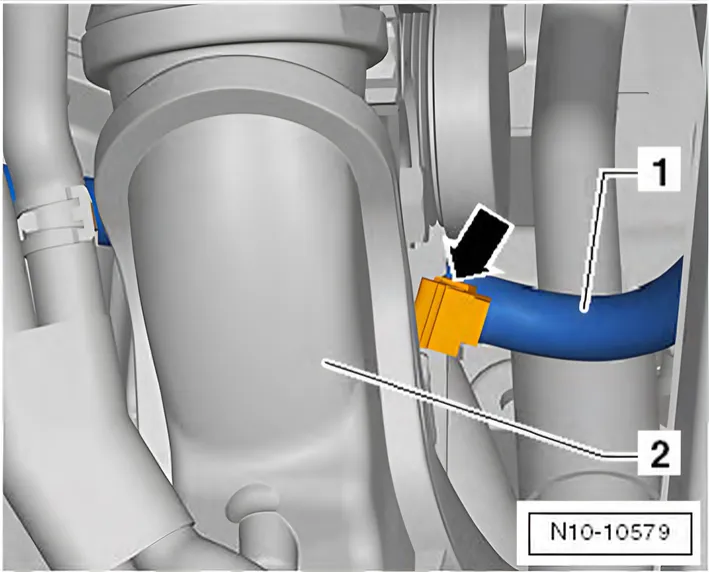
Vehicles with engine preheating element - Z97-
- Unclip wire -1- to engine preheater heater element - Z97- on charge air pipe -2- -arrow-.
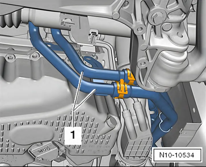
Vehicles with auxiliary/supplementary heater:
- Open hose clips, and pull coolant hoses off coolant pipes -1-.
- Remove auxiliary/supplementary heater with exhaust pipe and coolant hoses still connected ⇒ Auxiliary heater, supplementary heater; Rep. gr. 82; auxiliary/supplementary heater; Removing and installing auxiliary/supplementary heater.
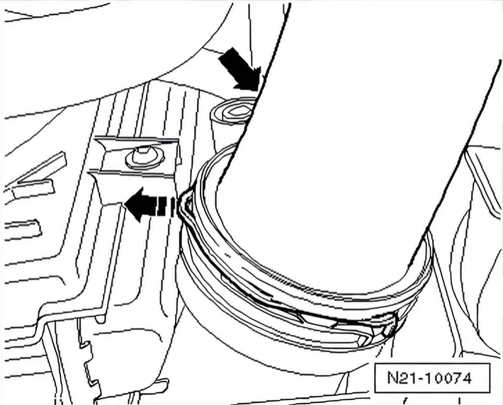
Continued for all vehicles:
- Pull off securing clip on charge air cooler in -direction of arrow-.
- Pull charge air hose -arrow- off charge air cooler.
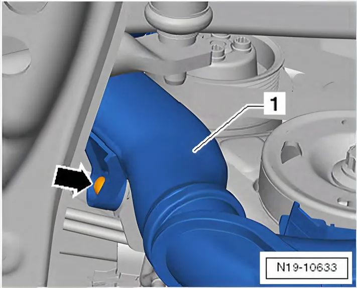
- Remove securing bolt -arrow- for charge air pipe -1-.
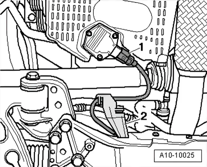
- Release and pull off connector -1- on oil level and oil temperature sender - G266-.
- Unclip bracket -2- on subframe for electric wire to oil level and oil temperature sender - G266-.
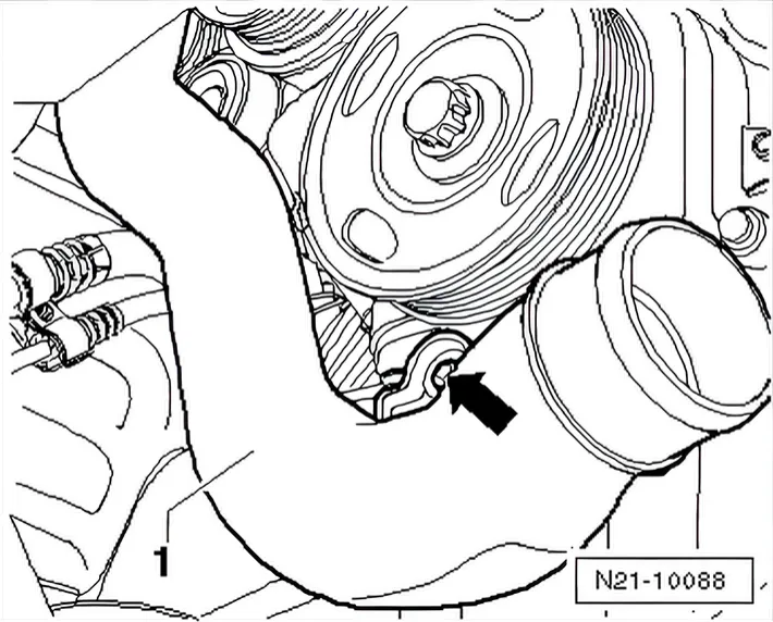
- Unscrew securing bolt -arrow- for charge air pipe -1-.
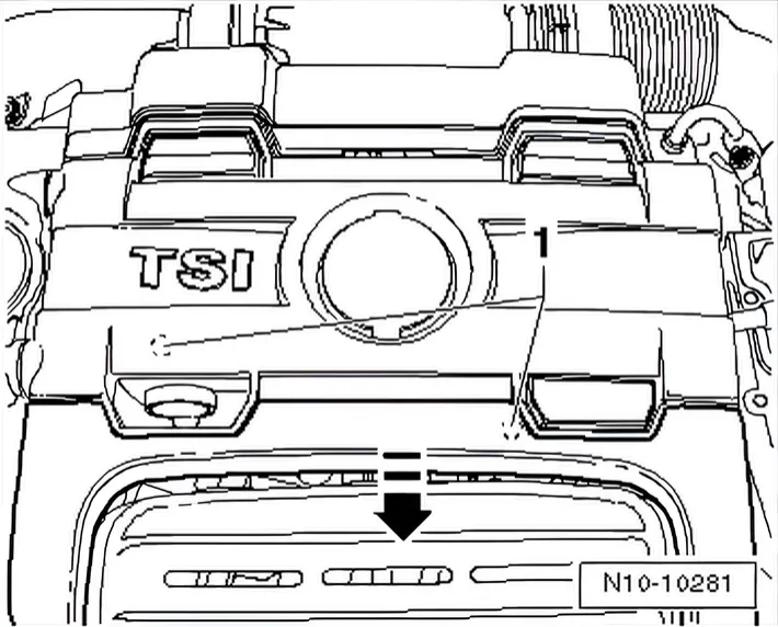
- Lift off engine cover at points -1- and pull it forwards in direction of -arrow-.
- Remove air filter housing ⇒ 1.3 Removing and installing air filter housing.
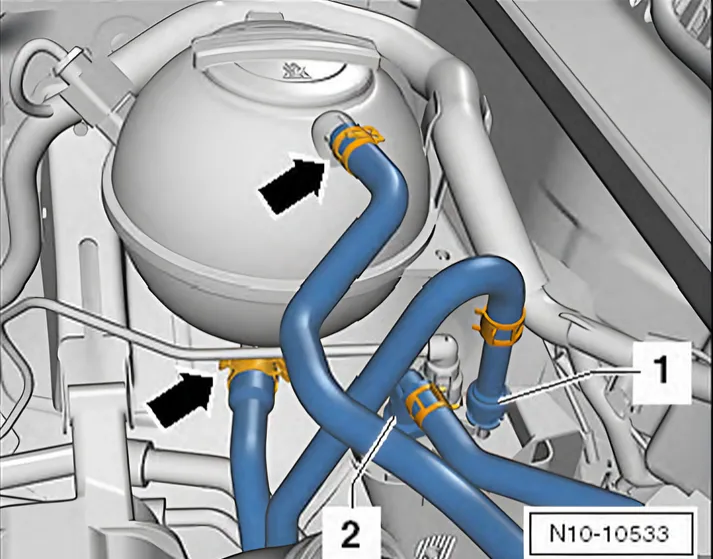
- Pull off fuel supply line -1- and line leading to activated charcoal filter -2- by pressing release tabs.
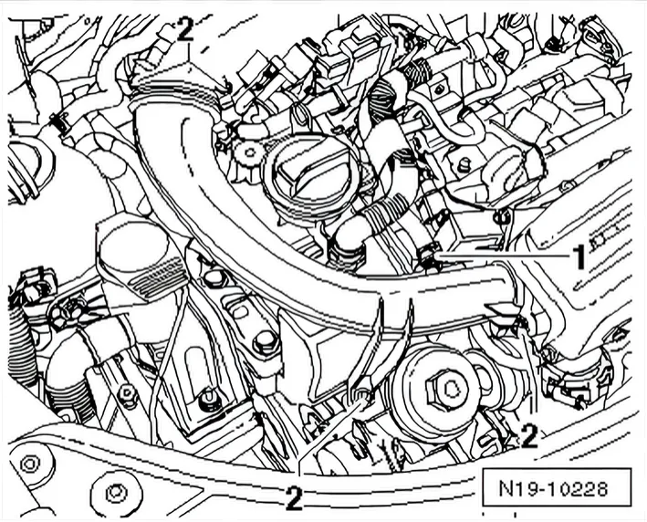
- Pull off hose -1- from pressure pipe.
- Unscrew securing bolts -2- from pressure pipe and remove pressure pipe.
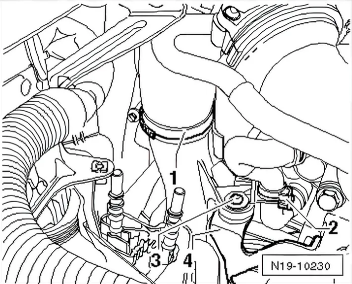
- Unscrew hose clip -1- on charge air pipe.
- Open hose retainer -2- and pull out hose.
- Unscrew securing bolt for charge air pipe -3- and pull off connector from charge air pressure sender - G31- with intake air temperature sender 2 - G299-.
- Remove bracket -4-.
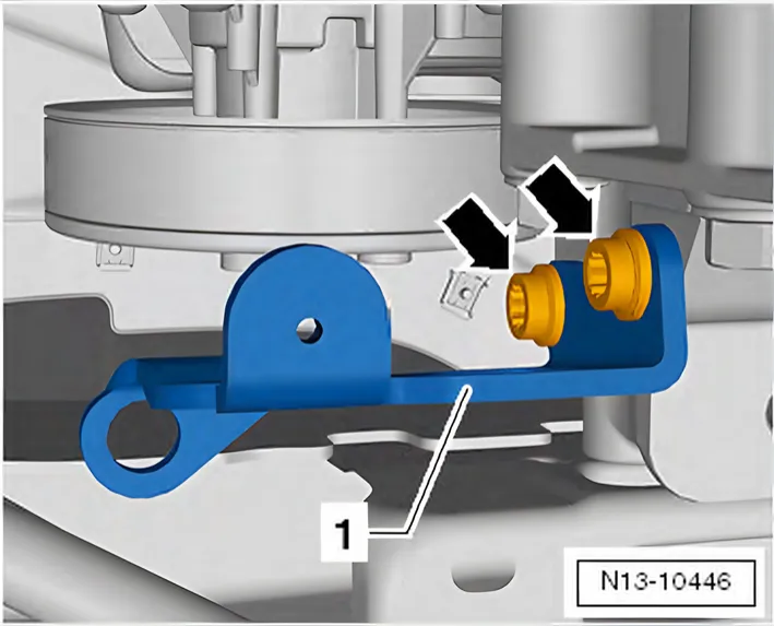
- To do this, unscrew bolts -arrows-.
- Remove bracket -1-.
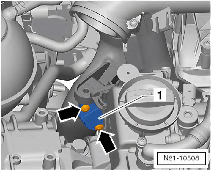
- Unscrew bolts -arrows- and remove charge pressure sender - G31- -1-.
- Remove charge air pipe downwards.
- Release connector -2- and pull off.
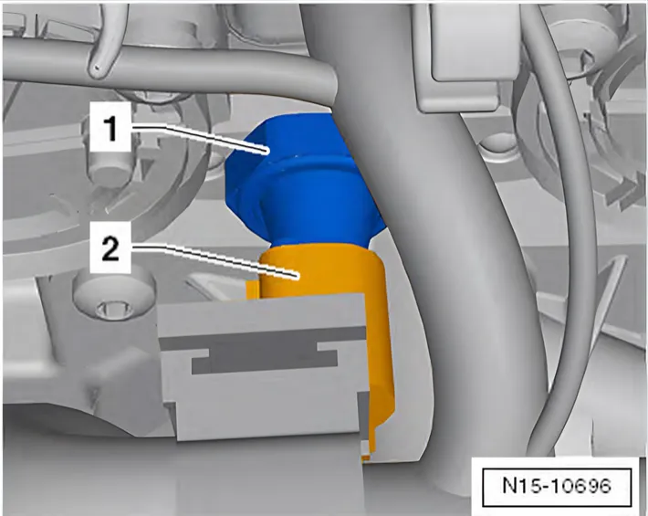
Disregard item -1-.
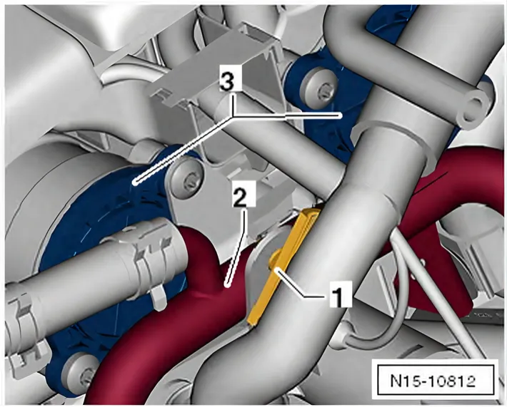
- Remove bolts for both camshaft covers -3-.
- Unclip wiring harness -1-.
- Pull coolant pipe -2- and wiring harness -1- away from cylinder head.
- Lever both camshaft covers -3- out of cylinder head.
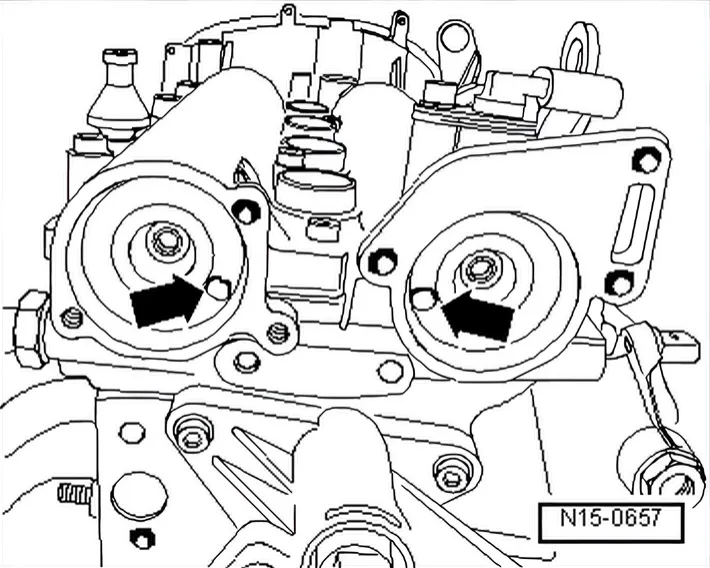
- The hole in the left exhaust camshaft -left arrow- must be positioned as shown in the illustration.
- If necessary, turn crankshaft in direction of engine rotation.
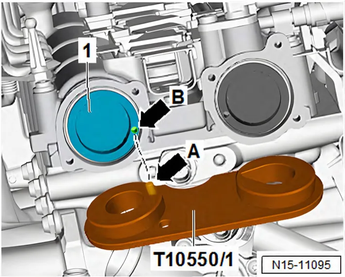
- Insert camshaft clamp - T10550/1- to stop in camshaft openings.
- The locking pin -arrow A- must engage in hole -arrow B- in exhaust camshaft.
- Inscription “TOP” must be readable from above.
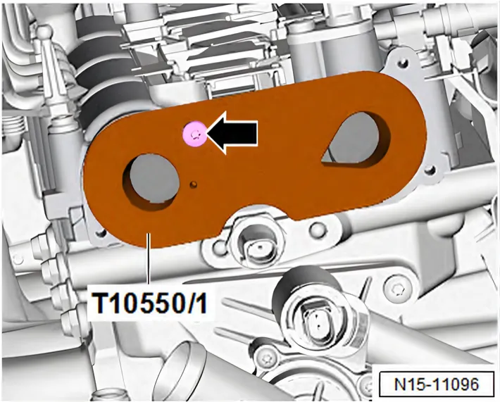
- Bolt on camshaft clamp - T10550/1- hand-tight.
- Use one bolt of the camshaft covers for this purpose -arrow-.
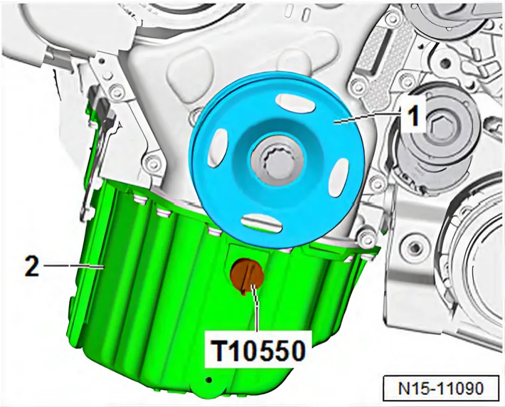
- Screw indicator - T10550/2- into hole in sump.
- Align centring point vertically so that the tip faces upwards.
- Tighten centring point with knurled nut.
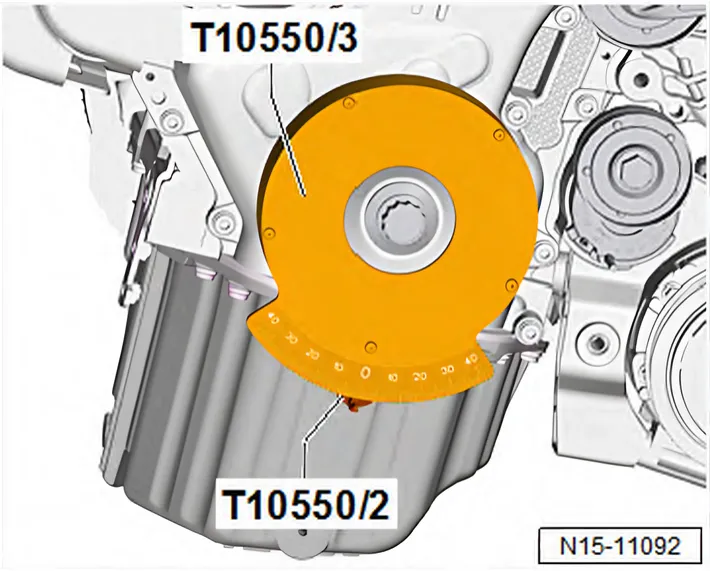
- Position scale sleeve - T10550/3- on belt pulley.
The scale sleeve - T10550/3- is equipped with magnets.
Proceed with great care when joining the components.
Note that the components are drawn together quickly by the magnetic force.
- Align scale sleeve - T10550/3- with indicator - T10550/2- as shown in illustration.
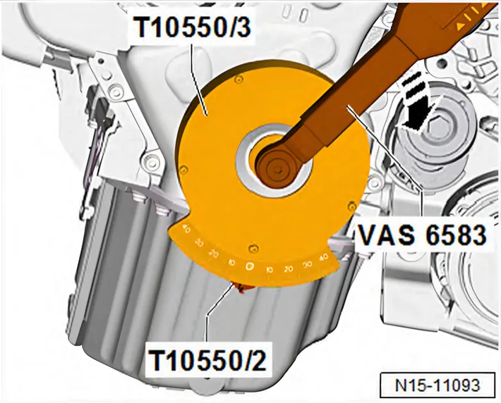
- Apply torque wrench - VAS 6583- with a suitable socket to crankshaft bolt.
- Push torque wrench - VAS 6583- clockwise and maintain a torque of 40 Nm on it.
- Set scale sleeve - T10550/3- and indicator - T10550/2- to »0«.
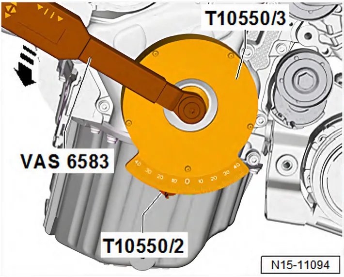
- Switch setting of torque wrench - VAS 6583-, and push it slowly anti-clockwise.
- Maintain a torque of 40 Nm on torque wrench - VAS 6583-.
- Read value on the scale.
- If the chain skips during the test, renew timing chain ⇒ 4.4 Removing and installing timing chain and chain drive for oil pump.
- If the chain skips, it can be heard and felt clearly.
Evaluation of the test
- If a chain elongation of up to 28° has been determined during the test, the timing chain is OK.
- If a chain elongation of 29° and more has been determined, the timing chain is not OK and must be renewed ⇒ 4.4 Removing and installing timing chain and chain drive for oil pump.
Assemble in reverse order of dismantling. During this procedure, observe the following:
- Turn scale sleeve - T10550/3- towards right by approx. 45° so that indicator - T10550/2- is not positioned within range of scale.
- Grasp behind scale sleeve - T10550/3- with both hands.
- Press thumbs against bolt of belt pulley, and pull off scale sleeve - T10550/3-.
- Renew oil seals for camshaft sealing cover and oil them before fitting.
- Add coolant ⇒ 1.6 Draining and filling coolant (Polo).
Specified torques
- ⇒ 1 Air filter
- ⇒ 2.1 Assembly overview - valve gear
- ⇒ 3 Charge air system
- ⇒ 2.1 Assembly overview - supercharger
- ⇒ 1.1 Assembly overview - poly V-belt drive
- ⇒ Body, front; Rep. gr. 50; Noise insulation, Assembly overview - noise insulation
- ⇒ General body repairs, exterior; Rep. gr. 66; Removing and installing wheel housing liner.
- ⇒ Running gear, axles, steering; Rep. gr. 44; Wheels, tyres