
1.2 TDI CR engine (EA189) · Mixture preparation – injection · Vacuum system
Vacuum system
2.1 Vacuum hose connection diagram
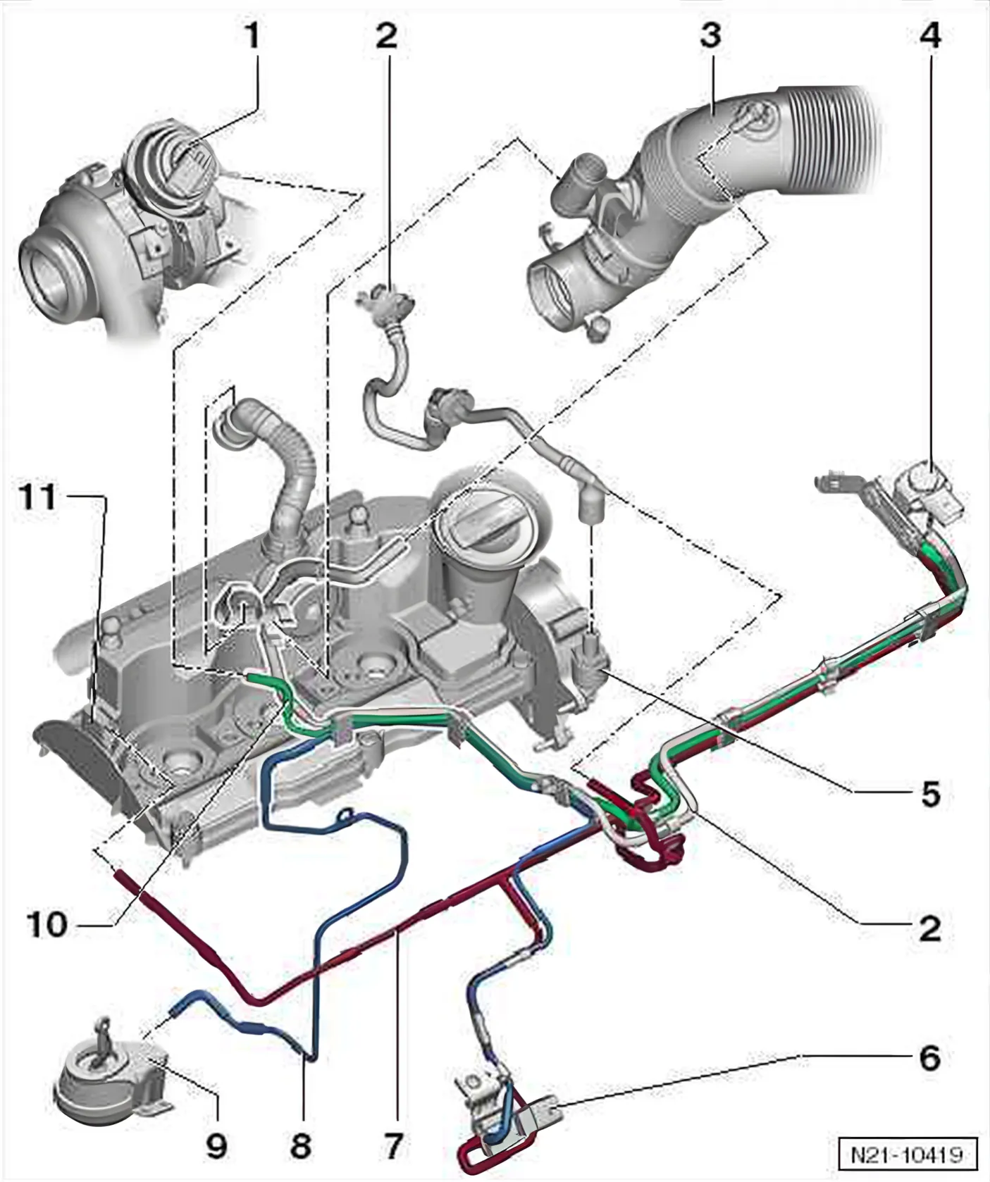
- 1 Vacuum actuator
- On turbocharger.
- With position sender for charge pressure positioner - G581-
- 2 Vacuum line
- To brake servo
- 3 Suction hose
- With connecting piece for ventilation line
- 4 Charge pressure control solenoid valve - N75-
- 5 Vacuum pump
- 6 Breather line to air filter housing
- 7 Exhaust gas recirculation cooler changeover valve - N345-
- Checking changeover ⇒ 3.2 Removing and installing exhaust gas recirculation cooler.
- 8 Vacuum line
- To cylinder head cover/vacuum tank
- 9 Vacuum line
- To vacuum unit at exhaust gas recirculation cooler
- 10 Vacuum actuator
- On exhaust gas recirculation cooler
- 11 Vacuum line
- To vacuum unit at exhaust turbocharger
- 12 Vacuum connection
- At cylinder head cover/vacuum reservoir
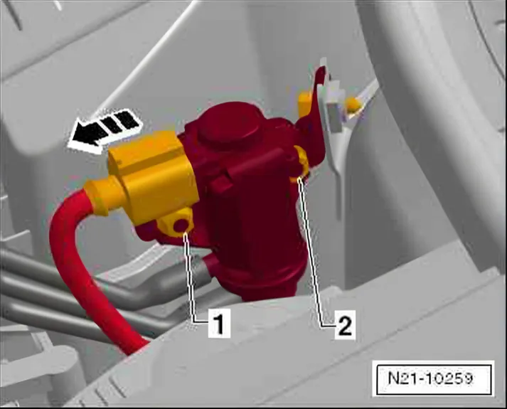
Removing charge pressure control solenoid valve - N75-
- Pull off connector -arrow-.
- Unscrew nuts -1 and 2-.
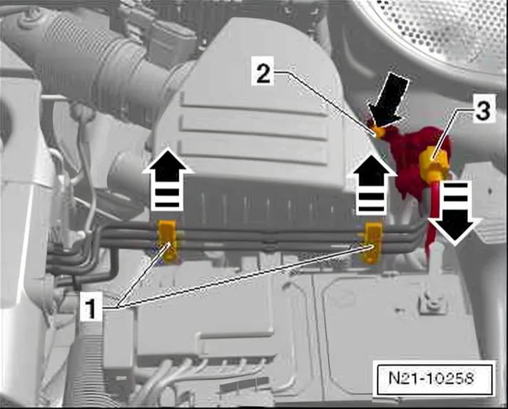
- Remove vacuum hoses with bracket -1- from air filter completely.
2.2 Checking vacuum system
Special tools and workshop equipment required
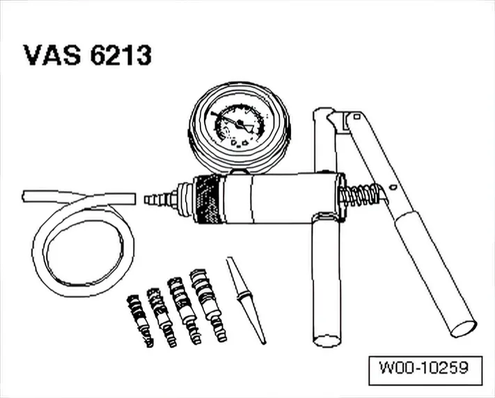
- Hand vacuum pump - VAS 6213-
Procedure
- Check all vacuum lines throughout entire vacuum system for:
- Cracks
- Marten bites
- Crushing
- Porous areas and other leaks
- Check vacuum line to solenoid valve and from solenoid valve to relevant component.
- If event is entered in memory, check vacuum lines to specified component, but also additionally the other vacuum lines to other components.
- If pressure cannot be built up using hand vacuum pump - VAS 6213- or pressure immediately drops again, check hand vacuum pump and connecting hoses for leaks.