
1.2 TDI CR engine (EA189) · Mixture preparation – injection · Intake manifold
Intake manifold
8.1 Assembly overview - intake manifold with attachments
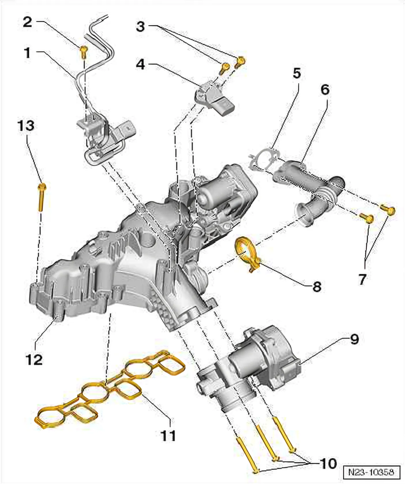
- 1 Exhaust gas recirculation cooler changeover valve - N345-
- 2 Bolt
- 8 Nm
- 3 Bolt
- 8 Nm
- 4 Charge air pressure sender - G31-
- 5 Seal
- Renew
- 6 Connecting pipe
- To cylinder head/exhaust gas recirculation cooler.
- 7 Bolt
- 9 Nm
- 8 Clip
- 4 Nm
- Renew
- 9 Throttle valve module - J338-
- 10 Bolt
- 10 Nm
- 11 Seal
- Renew
- Individual seals can also be installed.
- 12 Intake manifold
- With intake manifold flap control unit - GX14-
- With optimised swirl for intake air.
- Must not be dismantled.
- 13 Bolt
- 8 Nm
8.2 Removing and installing intake manifold
Special tools and workshop equipment required
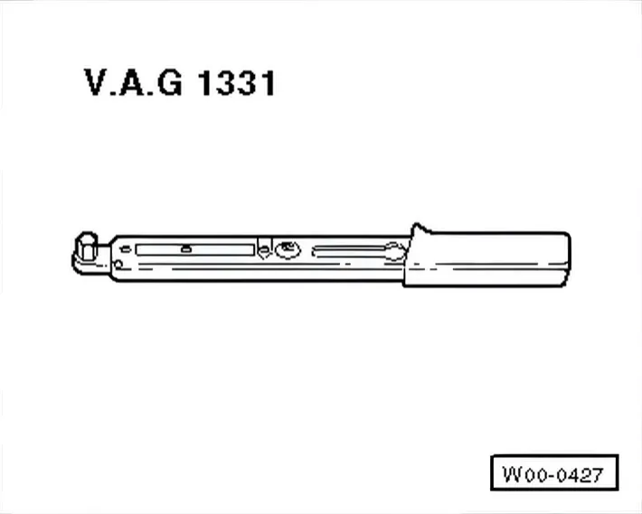
- Torque wrench - V.A.G 1331-
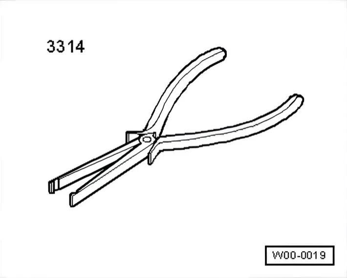
- Pliers - 3314-
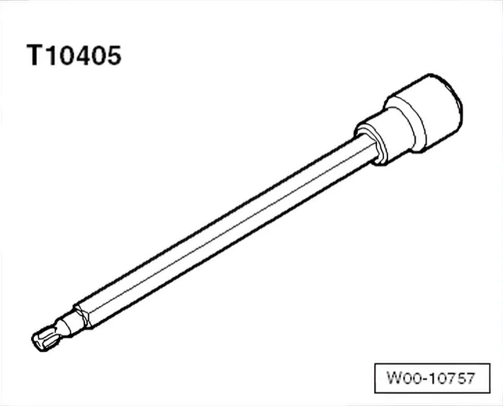
- Multi-point bit - T10405-
»Carry out the following work sequence«
Removing
- Remove engine cover panel ⇒ 3 Engine cover panel.
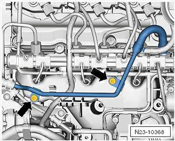
- Unscrew fuel return line bolts -arrows-.
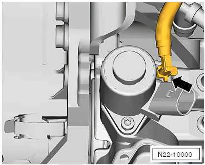
- Carefully release fuel return line at high-pressure pump -arrow-.
- Carefully pull fuel return line out of high-pressure pump.
- Pull connector off glow pin plugs ⇒ 28 – Glow plug system.
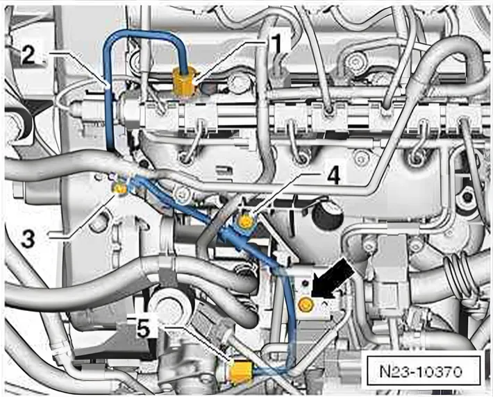
- Unscrew bolt -arrow-, and lay exhaust gas recirculation cooler changeover valve - N345- aside.
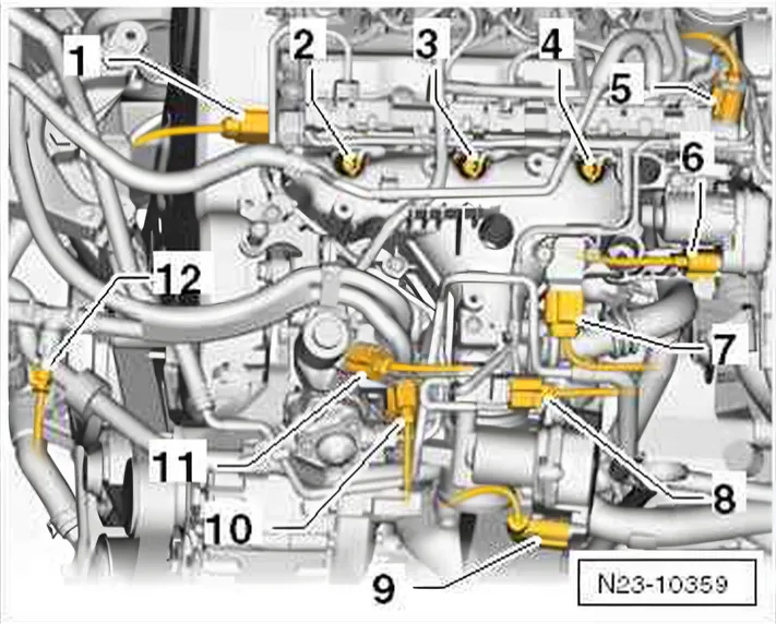
- Separate connectors -6, 7, 9, 11-.
- 6 Intake manifold flap control unit - GX14-
- 7 Charge air pressure sender - G31-
- 9 Throttle valve module - J338-
- 11 Fuel metering valve - N290-
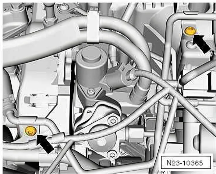
- Unscrew coolant return line bolts -arrows-.
- Lay coolant return line to side.
- Remove fuel rail ⇒ 3.6 Assembly overview - fuel rail.
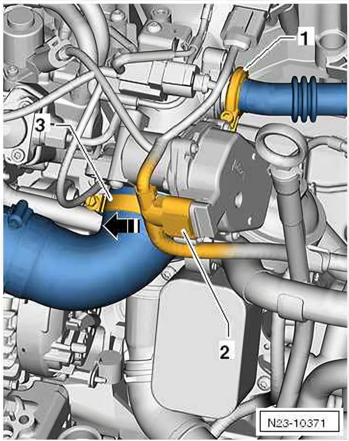
- Open clamps -1 and 3-.
- Unscrew intake manifold securing bolts ⇒ Item 13 (page 237) diagonally from outside to inside.
- Carefully remove intake manifold.
Installing
Install in reverse order of removal.
- Renew seals.
- Now insert securing bolts into holes in intake manifold.
- Carefully guide the intake manifold together with the seals and securing bolts to the installation location.
- Tighten intake manifold securing bolts diagonally from outside to inside. Specified torque ⇒ Item 13 (page 237).