
1.2 TDI CR engine (EA189) · Crankshaft group · Pistons and conrods
Pistons and conrods – assembly overview and fastening
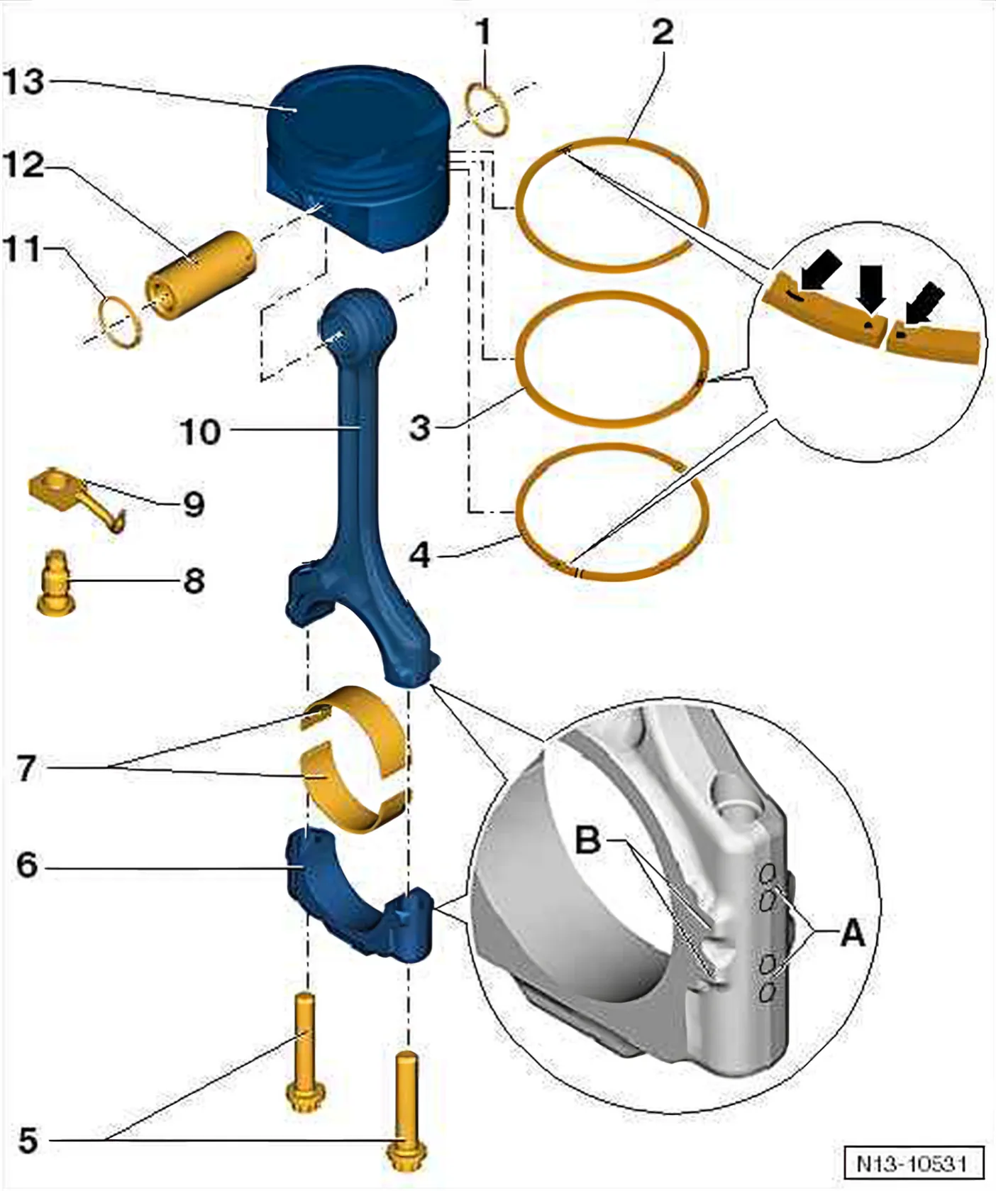
- 1 Retaining ring
- Renew
- 2 Piston ring
- compression ring
- Offset gaps by 120°
- Use piston ring pliers to remove and install.
- Installation position marking: “TOP” or side with lettering towards piston crown.
- Installation position: marking “dots or line” -arrows- towards piston crown.
- Measuring ring gap ⇒ 4.3 Measuring piston projection at “TDC”
- Measuring ring-togroove clearance ⇒ 4.4.1 Checking piston
- 3 Piston ring
- compression ring
- Offset gaps by 120°
- Use piston ring pliers to remove and install.
- Installation position marking: “TOP” or side with lettering towards piston crown.
- Installation position: marking “dots or line” -arrows- towards piston crown.
- Measuring ring gap ⇒ 4.3 Measuring piston projection at “TDC”
- Measuring ring-to-groove clearance ⇒ 4.4.1 Checking piston
- 4 Piston ring
- Oil scraper ring
- Offset gap 120° relative to lower compression ring
- Use piston ring pliers to remove and install.
- Installation position marking: “TOP” or side with lettering towards piston crown.
- Installation position: marking “dots or line” -arrows- towards piston crown.
- Measuring ring gap ⇒ 4.3 Measuring piston projection at “TDC”
- Measuring ring-to-groove clearance ⇒ 4.4.1 Checking piston
- 5 Bolt
- Renew
- Oil threads and contact surface
- 30 Nm +90°
- 6 Conrod bearing cap
- The conrod bearing cap only fits in one position and only on the appropriate conrod due to the breaking procedure (cracking) separating the cap from the conrod.
- Mark cylinder allocation in colour -B-.
- Installation position: markings -A- face towards belt pulley end.
- 7 Bearing bushes
- Fitting position ⇒ 4.4.1 Checking piston
- Mark used bearing shells for re-installation but not on bearing surface.
- Renew bearing shells worn down to base layer.
- Note version: upper bearing shell (towards piston) made of a more wear-resistant material. Identification on new bearing shells: black line on bearing surface in area of joint
- Ensure firm seating
- 8 27 Nm
- Bolt with pressure relief valve
- 9 Oil spray jet (for cooling of pistons)
- 10 Connecting rod
- Renew as set only.
- With industrially cracked conrod bearing cap
- Separate new conrod ⇒ 4.4.2 Cylinder bore
- Mark cylinder allocation in colour -B-.
- Installation position: markings -A- towards belt pulley end
- Axial clearance, wear limit: 0.37 mm
- Measuring radial clearance ⇒ 4.4.2 Cylinder bore
- 11 Retaining ring
- Renew
- 12 Piston pin
- If difficult to move, heat piston to approx. 60 °C.
- Remove and install using drift - VW 222 A-.
- 13 Piston
- With combustion chamber.
- Mark installation position and cylinder number ⇒ 4.4.1 Checking piston.
- Checking ⇒ 4.4.1 Checking piston
- Install using piston ring clamp.
- Piston and cylinder dimensions ⇒ 4.4.2 Cylinder bore.
- Measuring cylinder bore ⇒ 4.4.2 Cylinder bore
- Measuring piston projection at “TDC” ⇒ 4.3 Measuring piston projection at “TDC”