
Running gear, axles, steering · Steering · Steering rack
Removing and installing steering rack
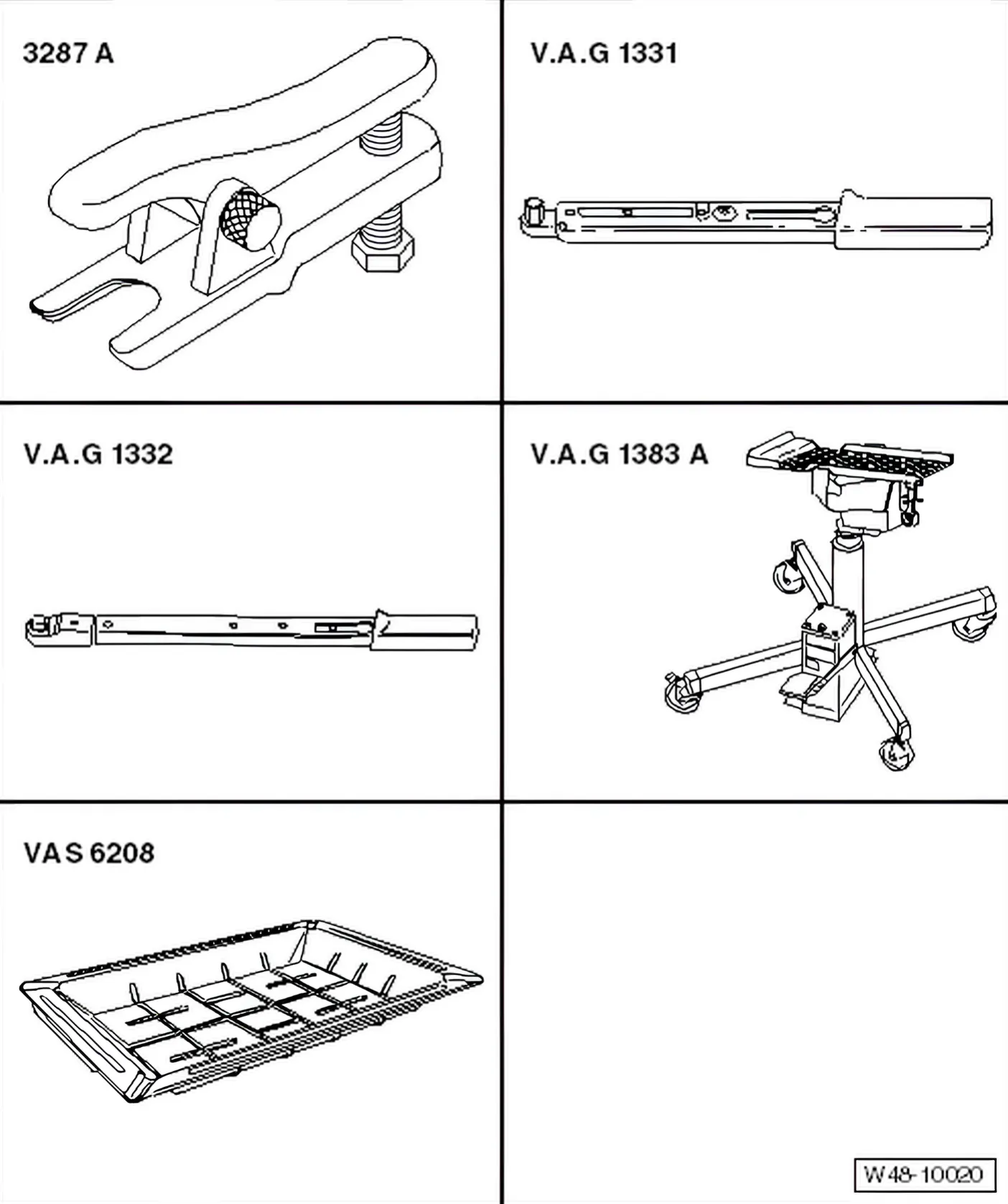
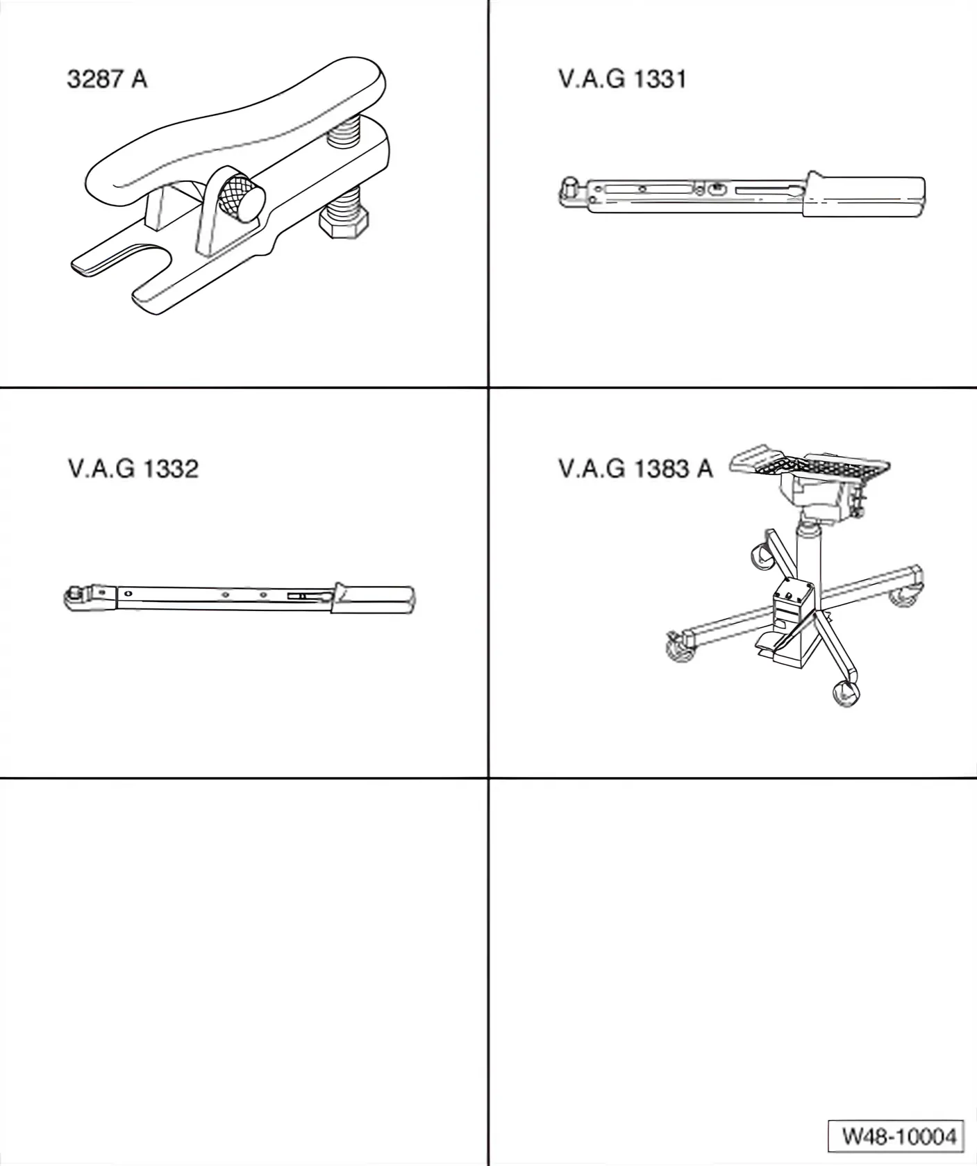
Special tools and workshop equipment required
- Ball joint puller - 3287 A-
- Torque wrench - V.A.G 1331-
- Flared ring spanner tool insert AF 17 - V.A.G 1331/10-
- Torque wrench - V.A.G 1332-
- Engine and gearbox jack - V.A.G 1383 A-
- Universal gearbox mounting - V.A.G 1359/2-
- 6R 2009–2014 Drip tray for workshop hoist - VAS 6208-
Removing
6R 2009–2014
- With ignition switched off, disconnect battery earth strap ⇒ Electrical system; Rep. gr. 27; Battery; Removing and installing battery.
Vehicles with air filter on left in engine compartment
- Remove battery and battery tray ⇒ Electrical system; Rep. gr. 27; Battery; Removing and installing battery.
Continued for all vehicles
- Lift vehicle far enough to take weight off front axle.
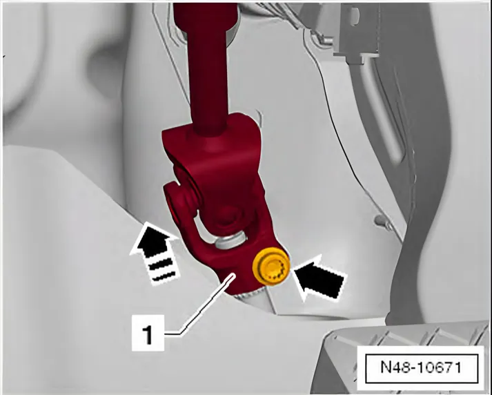
- Unscrew bolt -arrow- from universal joint -1- and pull off universal joint in -direction of arrow-.
- Loosen wheel bolts.
- Raise vehicle.
- Remove front wheels.
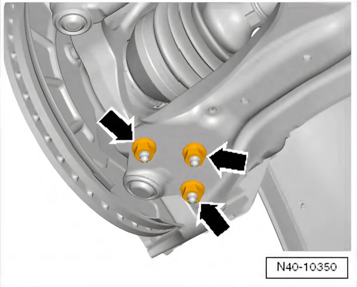
- Remove nuts -arrows-
- Pull swivel joint out of suspension link.
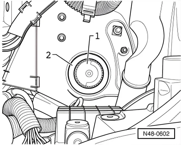
- Unscrew cap -1- from motor/pump unit -2-.
- Draw off as much hydraulic fluid as possible from motor/pump unit using a suction bottle.
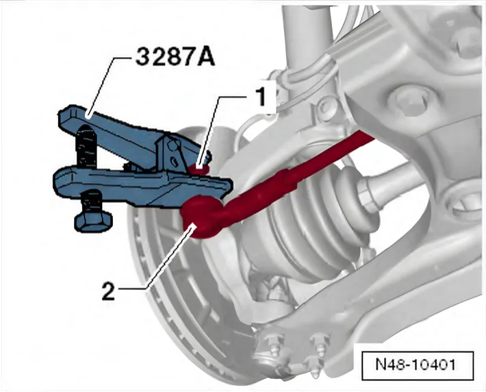
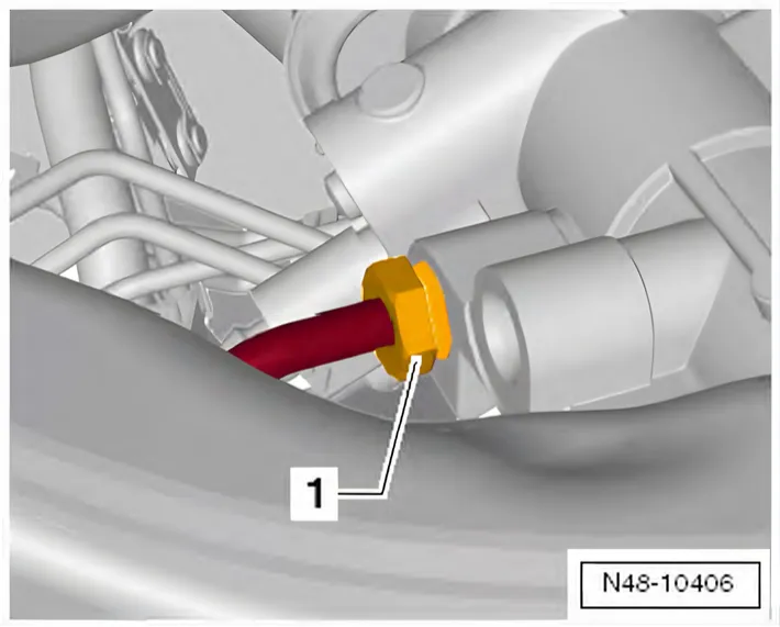
- Loosen nut -1- on track rod end -2- but do not remove completely.
- Press track rod ball joint -2- off steering arm.
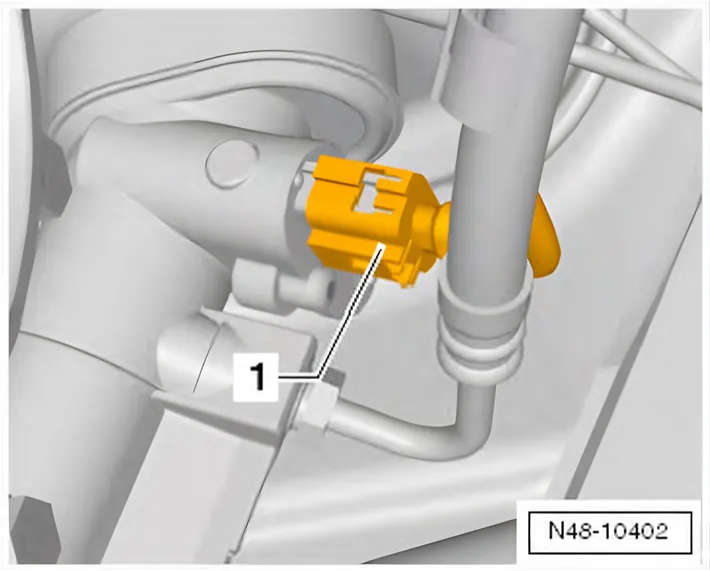
- If fitted, pull connector -1- off power steering sensor - G250-.
- Unscrew banjo bolt -1- (19 mm) for pressure line from steering rack.
- Close off line with a plastic bag and adhesive tape.
- Unscrew retaining screw -1- (17 mm) for return hose from steering rack.
- Close off line with a plastic bag and adhesive tape.
- Seal power steering rack threaded holes with plastic sealing plugs.
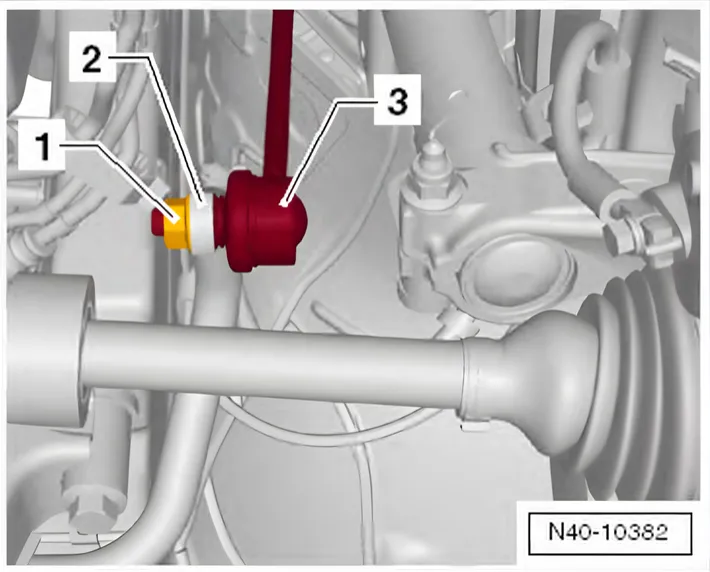
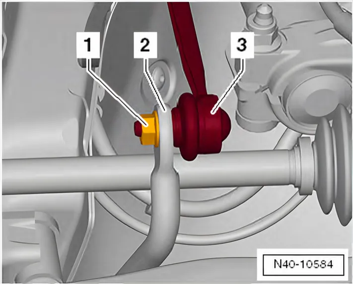
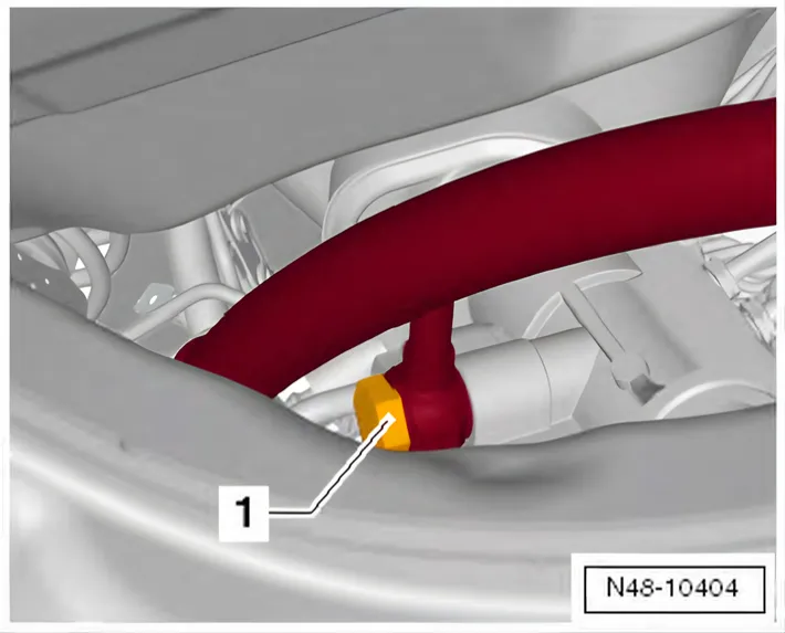
- Remove hexagon nut -1- from coupling rod (left and right sides).
- Pull coupling rod -3- out of anti-roll bar -2- on left and right sides.
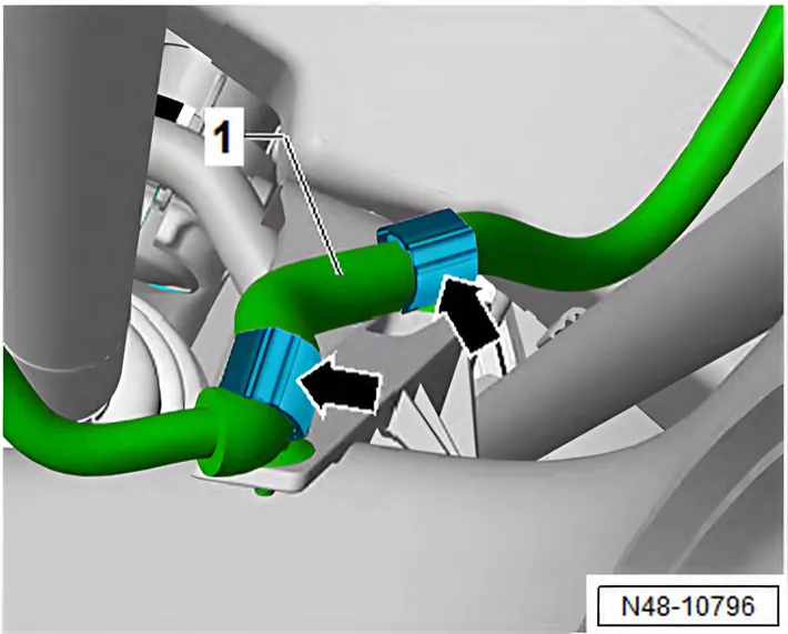
- Open clips -arrows- of retainer on subframe.
- Remove cable -1-.
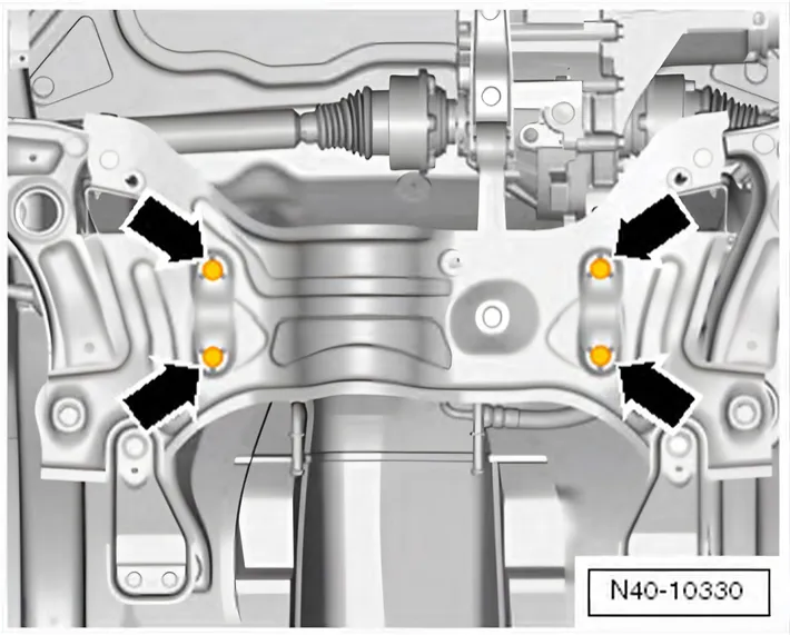
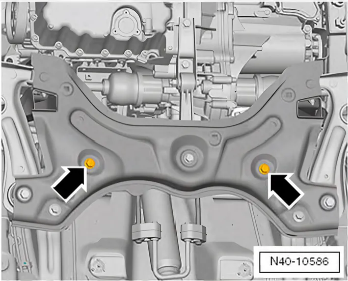
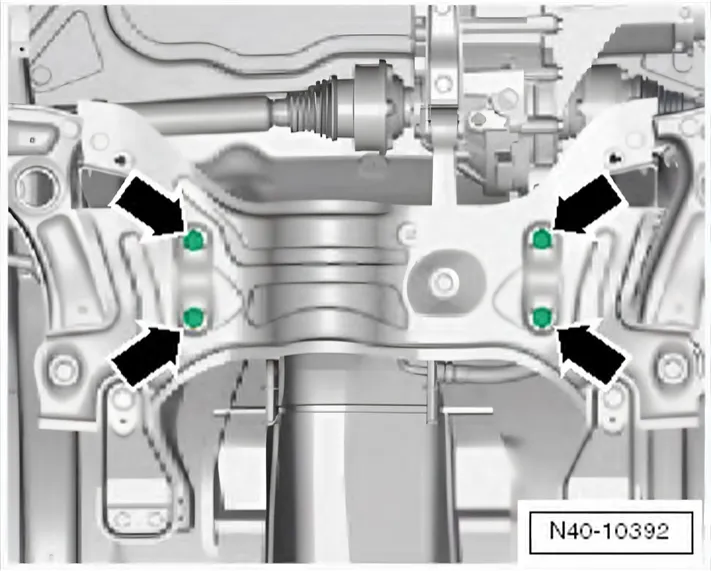
- Remove steering rack bolts -arrows- from subframe.
- Fix position of subframe ⇒ 2.2 Fixing position of subframe.
- Lower subframe using engine and gearbox jack - V.A.G 1383 A-.
- Take out steering rack towards the rear.
Installing
6R 2009–2014 Before inserting bolts for subframe, position power steering rack on subframe and insert power steering rack bolts.
6C 2014–2017 Install in reverse order. During this procedure, observe the following:
Steering rack must be moved to centre position before installing steering rack.
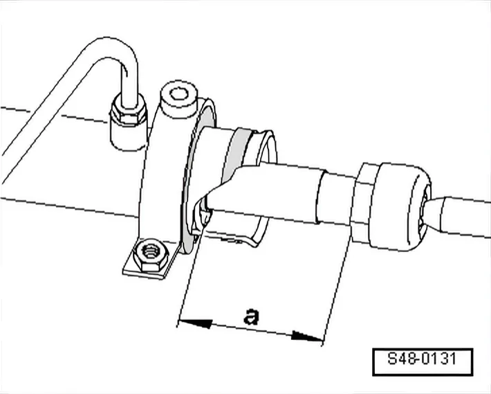
- Slide rack until dimension -a- is reached.
Dimension -a- = 72.5 mm
- 6R 2009–2014 Use new sealing rings for hose/line connections.
- Coat seal on steering rack with suitable lubricant, e.g. soft soap, before installing steering rack.
- After fitting the steering rack to the universal joint shaft ensure that the seal is not kinked against the assembly plate on the steering rack. The opening to the footwell must seal correctly. Otherwise, this can result in water leaks and/or noise.
- Ensure sealing surface is clean.
- When renewing the steering rack also install new boots on the track rods.
- 6C 2014–2017 Position steering rack on subframe.
- Start bolts for steering rack.
- Secure subframe ⇒ 2.2 Fixing position of subframe.
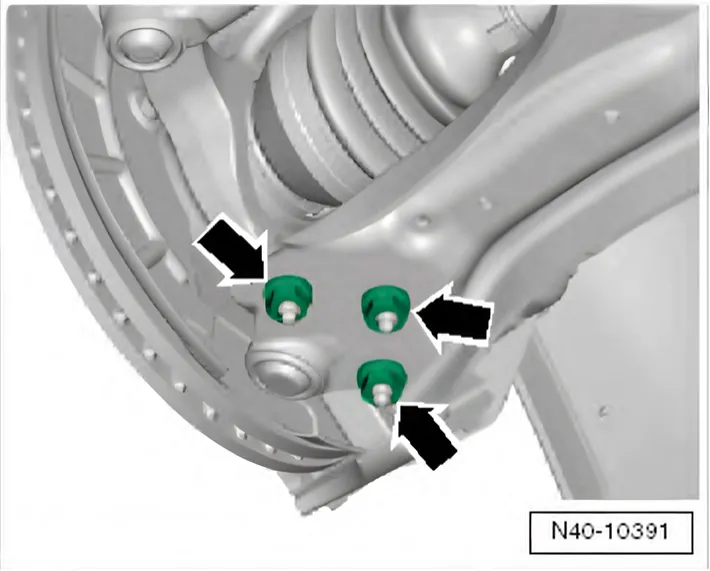
- Bolt swivel joint to suspension link with new nuts -arrows-.
Ensure that boot is not damaged or twisted.
6C 2014–2017
6C 2014–2017 Drawing as above ⇑
- Bolt steering rack to subframe -arrows-.
- Bolt track rod to steering arm.
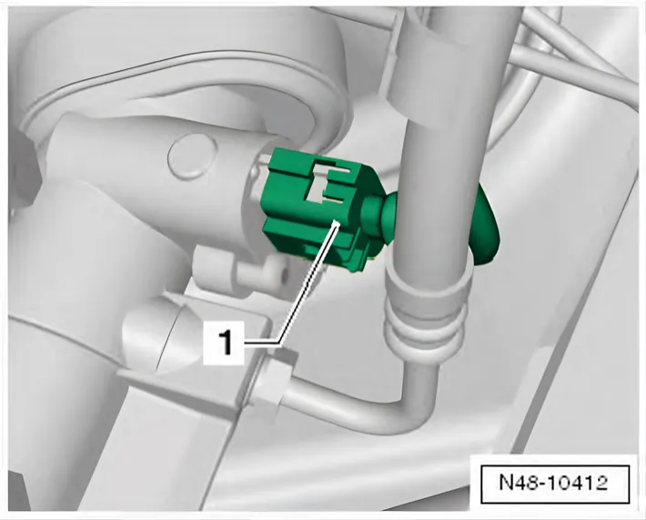
- If pulled off beforehand, connect connector -1- to power steering sensor - G250-.
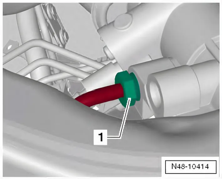
- Screw union bolt -1- (17 mm) for return hose onto steering rack.
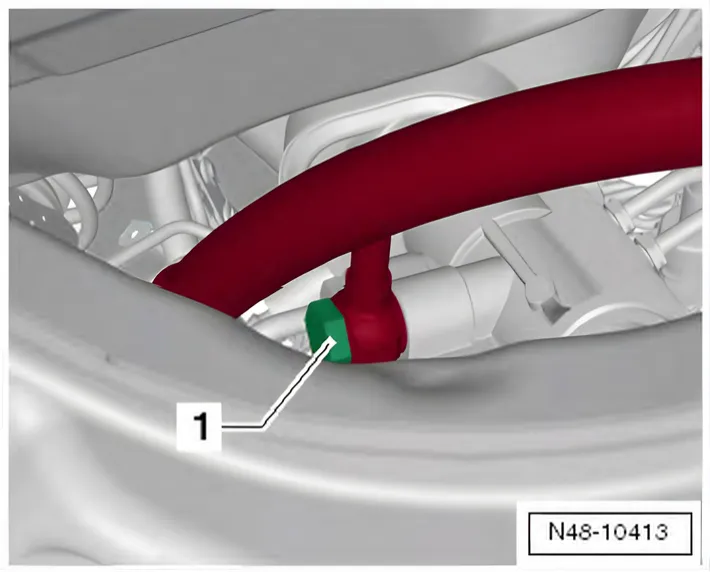
- Screw banjo bolt -1- (19 mm) for pressure line onto steering rack.
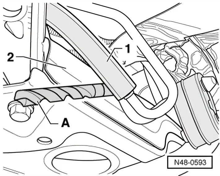
- If pressure line projects beyond subframe, adjust distance between pressure line and subframe.
- Distance between pressure line -1- and subframe -2- must be 10 mm.
- For example, check this with a drill bit -A- with a diameter of 10 mm by holding it between the pressure line -1- and the subframe -2-.
- Then tighten the banjo bolt for the pressure line.
Make sure that pressure line does not make contact with body or subframe.
- Use a hose (approx. 400…500 mm long) and a funnel to fill up with fresh hydraulic fluid.
- Use hydraulic fluid - G 004 000 M2-.
Vehicles with air filter on left in engine compartment
- Install battery and battery tray ⇒ Electrical system; Rep. gr. 27; Battery; Removing and installing battery.
Continued for all vehicles
After installation, check position of steering wheel during road test.
If steering wheel is not in straight-ahead position or if a new steering rack was installed, front axle tracking must be checked and if necessary adjusted!
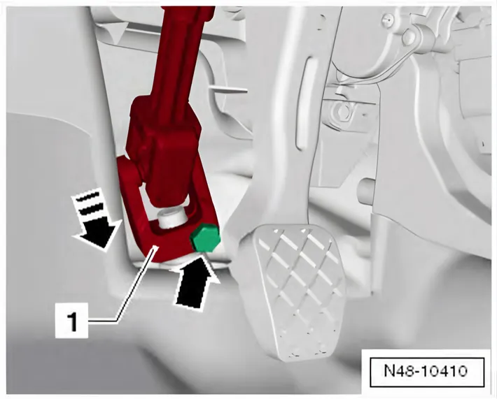
6C 2014–2017 Drawing as above ⇑
- Position universal joint -1- onto steering pinion.
- 6R 2009–2014 Connect earth strap of battery ⇒ Electrical system; Rep. gr. 27; Battery; Removing and installing battery.
- Insert new bolt -arrow- and tighten.
- Install wheels and tighten bolts or nuts ⇒ 1.5 Specified torques for wheel bolts.
- 6R 2009–2014 Bleed steering system ⇒ 7 Bleeding steering system, checking for leaks and checking fluid level.
- Check hydraulic fluid level ⇒ 7.3 Checking hydraulic fluid level of power steering.
6C 2014–2017 If the steering wheel is found to be off centre during the road test even though locating pins - T10096/ T10486/1- were used, check wheel alignment. In this case the wheel alignment test results must be archived in the vehicle files.
- Check toe adjustment ⇒ 3 Wheel alignment.
Specified torques
| Component | Specified torque |
|---|---|
| 6R 2009–2014 Swivel joint to suspension link ♦ Use new bolts | 100 Nm |
| 6C 2014–2017 Swivel joint to suspension link ♦ Use new bolts | 40 Nm +45° |
| 6R 2009–2014 Steering box to subframe ♦ Use new bolts | 50 Nm +90° |
| 6C 2014–2017 Steering box to subframe ♦ Use new bolts | 50 Nm +180° |
| Track rod to steering arm | 20 Nm +90° |
| 6R 2009–2014 Power steering sensor - G250- in steering rack | 6 Nm |
| 6R 2009–2014 Union screw for return line to steering rack ♦ Use new seals. | 30 Nm |
| 6R 2009–2014 Banjo bolt for pressure line to steering rack ♦ Use new seals. | 40 Nm |
| 6R 2009–2014 Universal joint to steering rack ♦ Use new bolt | 30 Nm |
| 6C 2014–2017 Universal joint to steering rack ♦ Use new bolt | 20 Nm +180° |
The two manuals give different torques for the same swivel joint nuts (N10332002): 100 Nm in the Polo 6R manual, 40 Nm +45° in the Polo 6C manual. Other cars with the same swivel joints differ too: the Audi A1 8X manual gives 100 Nm, the Škoda Fabia II manual 40 Nm +45°.
Different steering racks: the 6R has electro-hydraulic power steering, the 6C electromechanical. The bolts are tightened to different angles.
Different bolts: the Polo 6R manual tightens the intermediate steering shaft to the steering rack to 30 Nm, the Polo 6C manual to 20 Nm +180° (assembly overview, steering column).
6C 2014–2017
- ⇒ 2.1 Assembly overview - subframe
- ⇒ 2.1 Assembly overview - steering column
- ⇒ 3.1 Assembly overview - steering rack
6R 2009–2014 Removing and installing power steering sensor - G250- , left-hand drive vehicle
Special tools and workshop equipment required
Removing
- Pull connector -1- off power steering sensor - G250-.
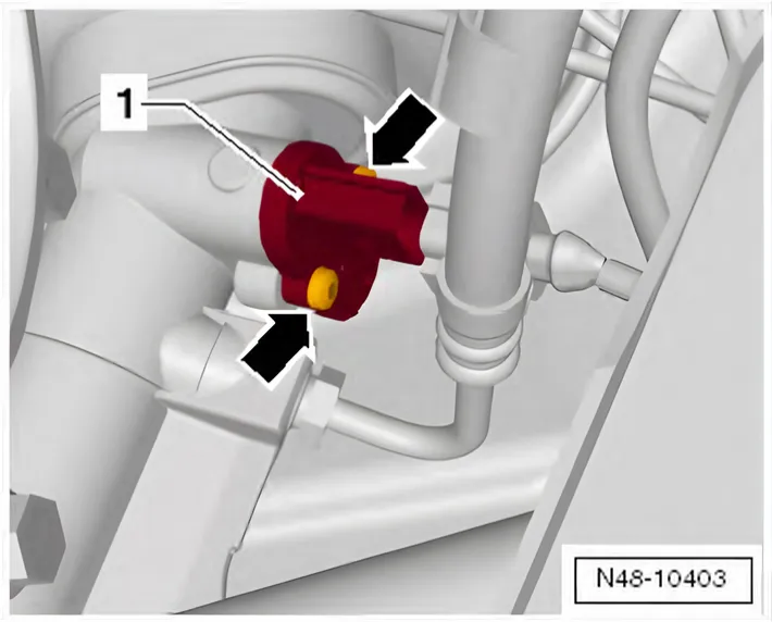
- Unscrew bolts -arrows-.
- Pull out power steering sensor - G250- -1- from steering rack.
Installing
Carry out installation in the reverse sequence, noting the following:
- Install new seal on power steering sensor - G250-.
Specified torques
| Component | Specified torque |
| Power steering sensor - G250- in steering rack | 6 Nm |
Determining centre position of steering rack
Rack must be positioned in centre before installing power-assisted steering rack.
- Slide steering rack until dimension -a- is reached.
Dimension -a- = 75.5 mm