
1.4 TSI engine (EA111) · Turbocharging/supercharging · Exhaust turbocharger
Adjusting vacuum unit for turbocharger
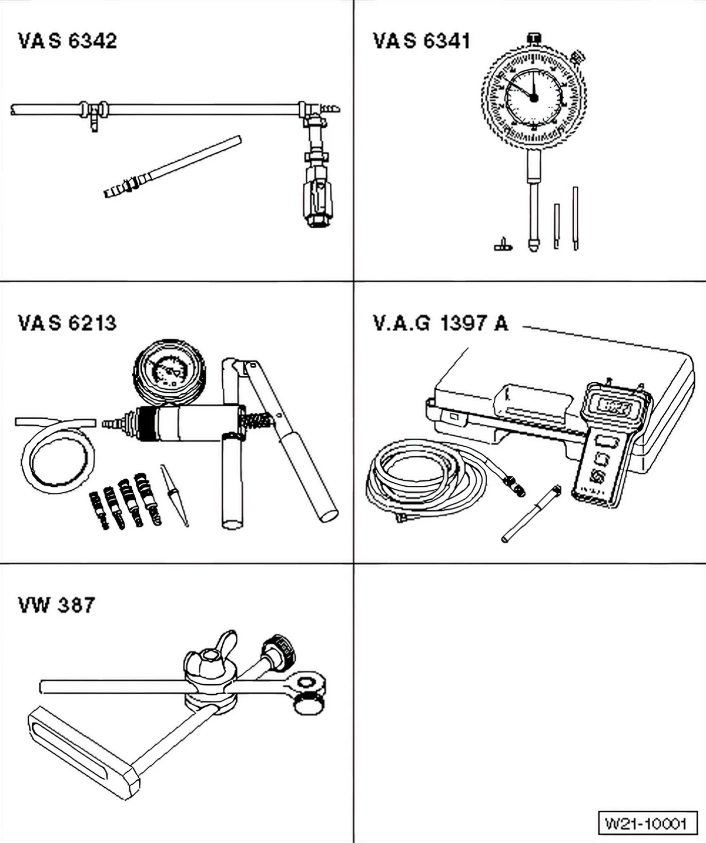
Special tools and workshop equipment required
- Pressure regulating valve - VAS 6342-
- Dial gauge set, 4-part - VAS 6341-
- Hand operated vacuum pump - VAS 6213-
- Turbocharger tester - V.A.G 1397A-
- Universal dial gauge holder - VW 387-
- Dial gauge extension, 30 mm - VAS 6341/3- (not shown)
- Flat pickup - VAS 6341/4- (not shown)
Procedure
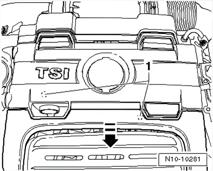
- Lift engine cover panel at points -1- and pull it forwards in direction of -arrow-.
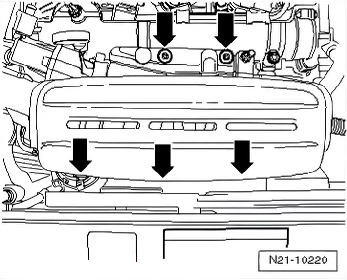
- Unbolt heat shield over turbocharger -arrows-.
- Open and close expansion tank cap to release pressure in cooling system.
- Now drain coolant.
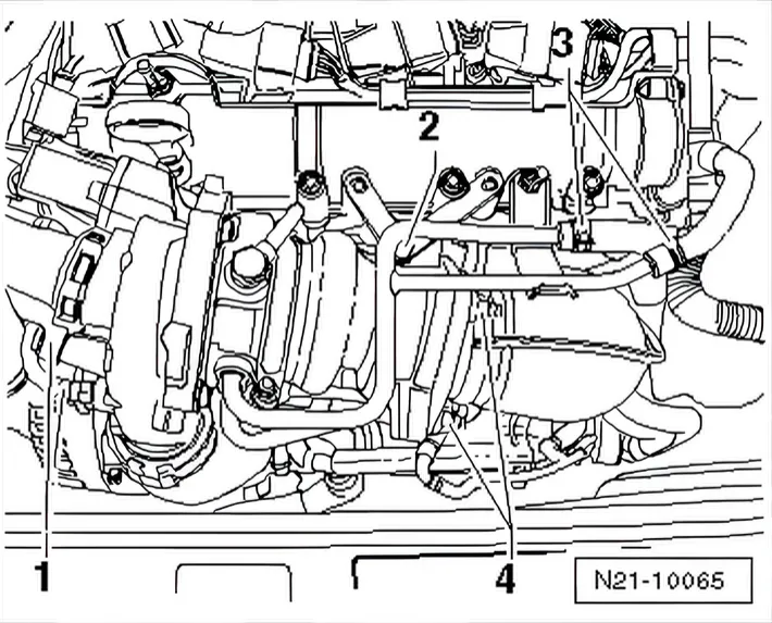
- Pull off connecting hoses -1- and coolant hoses -3-.
- Remove bolts and securing nuts -4- from turbocharger.
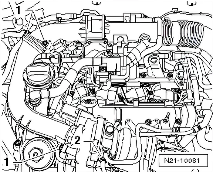
- Unscrew securing bolt -2- and remove upper coolant pipe.
- Unscrew bolts -1- and remove pressure pipe.
- Depending on vehicle equipment, remove noise insulation or skid plate ⇒ General body repairs, exterior; Rep. gr. 50; Removing and installing noise insulation or skid plate.
- Remove wiring for Lambda probe after catalytic converter - G130- and for alternator from cable guides -arrows-.
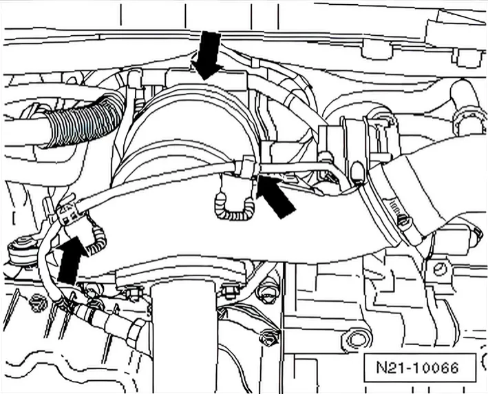
- Pull connector off Lambda probe after catalytic converter - G130- and remove.
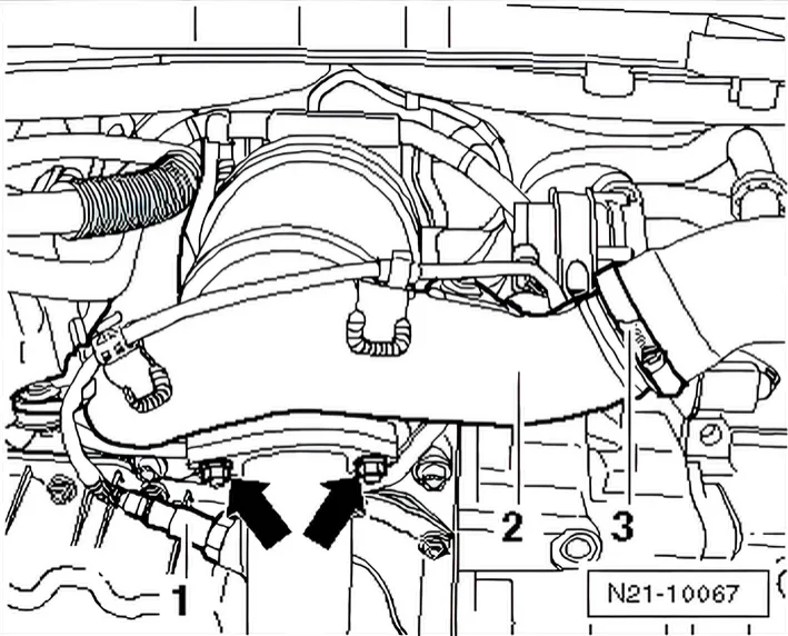
- Open hose clip -3- and remove charge air pipe -2-.
- Unbolt exhaust pipe from catalytic converter -arrows-.
- Remove catalytic converter downwards.
- Pull hose -arrow- from vacuum unit on turbocharger.
Checking vacuum unit adjustment ⇒ 1.3 Checking vacuum unit for turbocharger.
Continuation if the vacuum unit has been renewed or the linkage loosened
- Remove sealing paint from lock nut -2-.
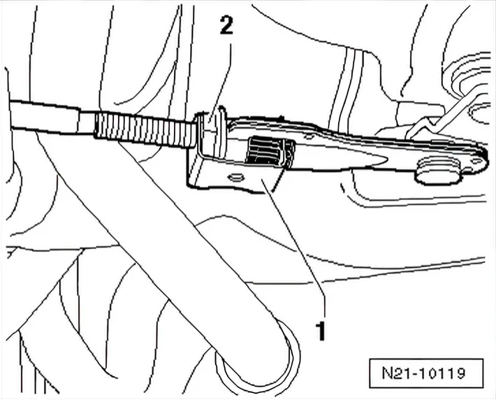
- Pull off retaining clip -1- and loosen lock nut -2- on vacuum unit linkage.
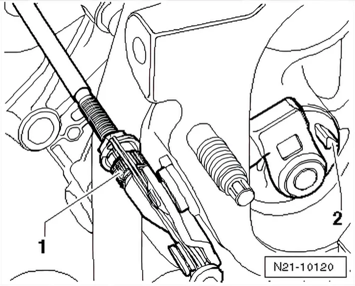
- Pre-adjust bypass flap -2- on vacuum unit linkage -1- via knurled screw, so that bypass flap can just be turned by hand.
- Turn knurled nut -1- 2 turns further.
- Tighten lock nut hand-tight.
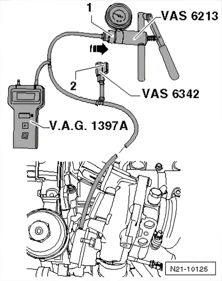
- Connect hand vacuum pump - VAS 6213-, turbocharger tester - V.A.G 1397A- to connection -II- and pressure control valve - VAS 6342- as shown in illustration.
- Close pressure control valve - VAS 6342- at lever -2-.
- Push sliding ring -1- on hand vacuum pump - VAS 6213- to pressure gauge in direction of -arrow-.
- Switch on turbocharger tester - V.A.G 1397A- and set sliding switch to position -II-.
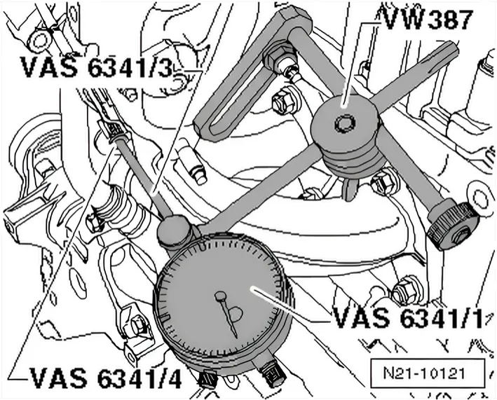
- Secure universal dial gauge bracket - VW 387- to turbocharger.
- Secure dial gauge - VAS 6341/1- with dial gauge extension, 30 mm - VAS 6341/3- and flat pickup - VAS 6341/4- to universal dial gauge bracket - VW 387-.
- With pressure at 0 bar, set dial gauge - VAS 6341/1- to 1 mm preload.
- Operate hand vacuum pump - VAS 6213- until a pressure of 800 mbar is displayed on turbocharger tester - V.A.G 1397A-.
- Vent system via pressure control valve - VAS 6342- so that pressure reading drops to 0 mbar.
- Repeat this procedure approx. 3-5 times.
- Vent system via pressure control valve - VAS 6342- so that pressure reading drops to 0 mbar.
- Set dial gauge - VAS 6341/1- to 0.
- Operate hand vacuum pump - VAS 6213- until turbocharger tester - V.A.G 1397A- indicates 500 +/- 5 mbar.
- Read off and note value indicated on dial gauge - VAS 6341/1-.
- Operate hand vacuum pump - VAS 6213- until turbocharger tester - V.A.G 1397A- indicates 800 +/- 5 mbar.
- Vent system via pressure control valve - VAS 6342- so that pressure reading drops to 500 +/- 5 mbar.
- Read off and note value indicated on dial gauge - VAS 6341/1-.
- Add values 1 and 2 together and divide by 2.
- The result (mean value) should be 5.5 +/- 0.25 mm.
- Correct setting if the result (average) is not 5.5 +/- 0.25 mm, tighten lock nut hand-tight and repeat measurement.
- If the result (mean value) is 5.5 +/- 0.25 mm, tighten the lock nut to 9 Nm and secure with sealing paint.
- Secure retaining clip to vacuum unit linkage.
Installation is carried out in the reverse order. When installing, note the following:
- Renew seals, gaskets and self-locking nuts.
- Hose connections and hoses for charge air system must be free of oil and grease before assembly.
- Secure all hose connections with hose clips which conform to production standard.
- If renewed, place seal in groove of charge air hose. Ensure seal is correctly seated in groove.
- Lightly moisten seal with engine oil.
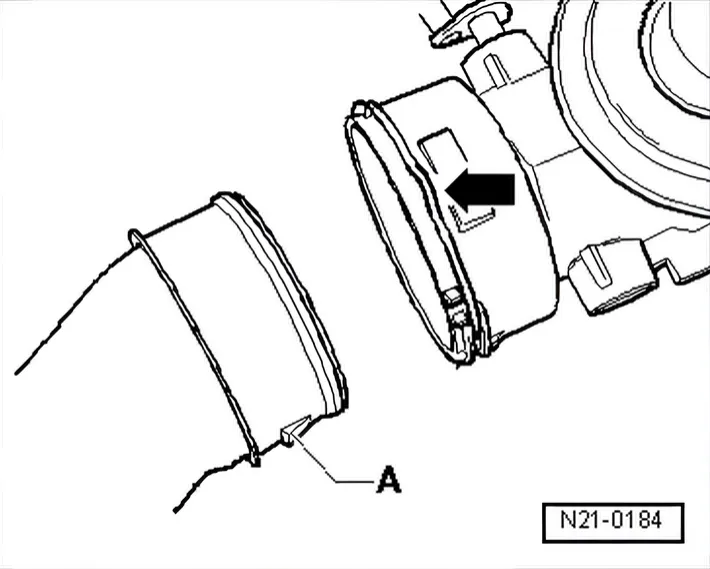
- Bring retaining clip to release position -arrow-.
- When installing air pipes with plug-in connector, ensure that securing clip -arrow- audibly engages into retaining lug -A-.
Assembly overview - turbocharger ⇒ 1.1 Assembly overview - turbocharger.
Assembly overview - charge air system ⇒ 3 Charge air system
Removing and installing parts of exhaust system ⇒ 26 – Exhaust system