
Running gear, axles, steering · Wheels, tyres, vehicle geometry · Adaptive cruise control
Calibrating adaptive cruise control
Only 6C 2014–2017
Before adjusting the adaptive cruise control (ACC) system, check the sensor, its bracket and its securing elements for damage, external influence and secure seating. Repair any damaged parts if necessary.
Before adjusting the adaptive cruise control (ACC) system, read out the event memory and rectify any faults found.
The “measured misalignment-angle value” of the ACC control unit indicates whether or not the sensor is out of adjustment.
Use only a wheel alignment machine and adjusting devices approved by VW/AUDI to adjust the adaptive cruise control (ACC) system.
Correct adjustment is an essential prerequisite for the perfect functioning of the adaptive cruise control (ACC) system.
Special tools and workshop equipment required
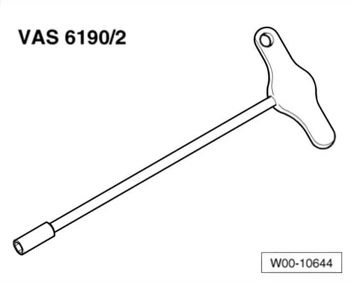
- Adjusting tool - VAS 6190/2-
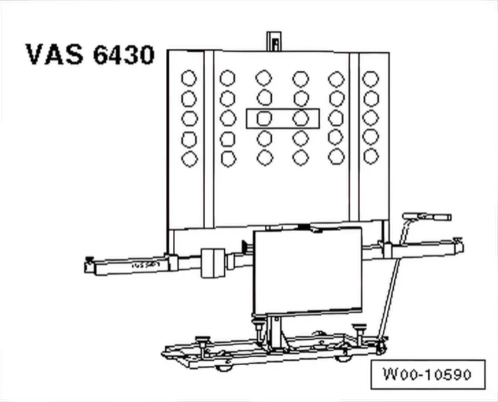
- Setting device - VAS 6430- or setting device, basic kit - VAS 6430/1-
- ACC reflector mirror - VAS 6430/3-
- Wheel alignment computer
Adjustment procedure described here is based on adjustment device - VAS 6430-.
The following setting sequence is to be adhered to:
- 1 Establish a distance of 120 cm ± 2.5 cm between the ACC
reflecting mirror - VAS 6430/3- fitted in the middle and the sensor in the radiator grille.
- 2 Install ACC reflector mirror - VAS 6430/3- centred on align‐
ment beam.
- 3 Adjust adaptive cruise control unit - J428-.
If wheel alignment has just been carried out, the steps described under “Setting without preceding wheel alignment” do not have to be carried out.
Setting without preceding wheel alignment
- Press button to select ACC calibration in wheel alignment computer.
- Note testing preconditions for wheel alignment ⇒ 3.2 Conditions for testing.
- Drive car onto wheel alignment platform.
- Connect battery charger ⇒ Electrical system; Rep. gr. 27; Battery; Disconnecting and reconnecting battery.
- Connect ⇒ Vehicle diagnostic tester. (Route diagnostic cable through open window.)
- Move front wheels to straight-ahead position.
- Mount quick-release clamps on rear wheels.
- Mount measurement transducers on rear wheels.
- Carry out wheel run-out compensation at rear wheels.
Setting with or without preceding wheel alignment
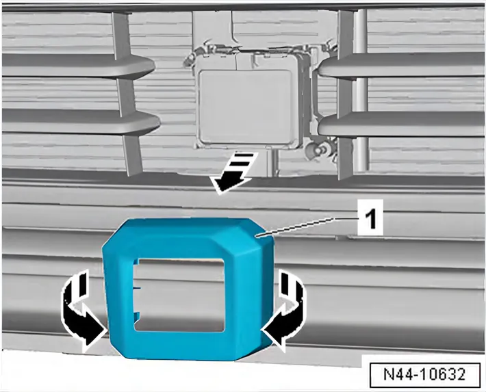
- Remove trim -1-.
- Remove dirt, if there is any, from the sensor lens.
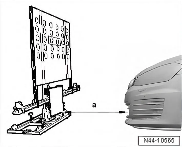
- Position ACC setting device - VAS 6430/3- centrally and parallel at a distance -a- from centrally fitted ACC reflector mirror
- VAS 6430/3- to adaptive cruise control unit - J428-.
a - 120 cm ± 2.5 cm
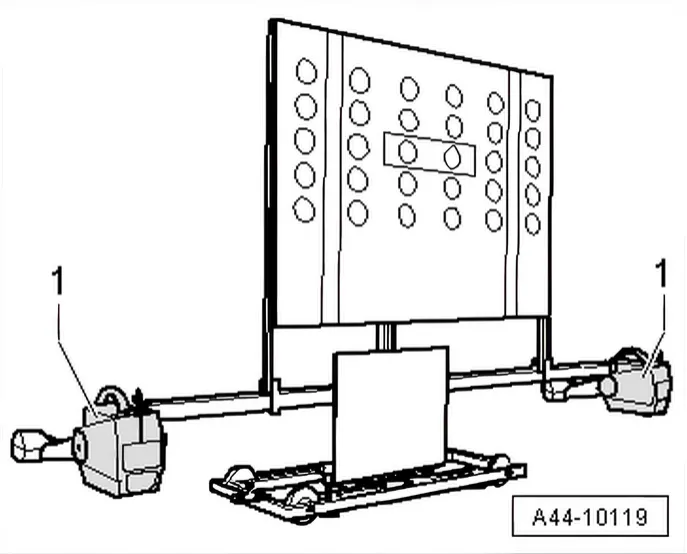
Sequence of steps for all
- Mount measurement transducers -1- of front wheels on alignment beam.
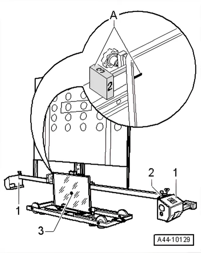
- In the area -A-, move position -2- on rotary knob so that it coincides with marking on mirror (the number 2 on the rotary knob must point towards the vehicle).
- Use adjusting screws -1-, -2- and -3- to bring spirit levels -A- and -B- to - VAS 6430/3- horizontal.
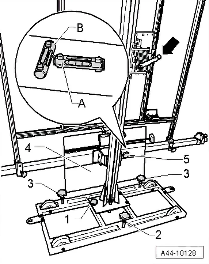
- Adjust mirror -4- by means of crank handle -arrow- in such a way that the laser beam contacts the centre of the sensor lens.
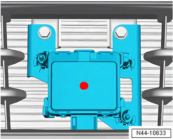
- Position the mirror on side of the alignment beam so that the laser beam contacts the centre of the sensor lens.
- Turn fine adjuster screw -5- until display on wheel alignment computer is within tolerance.
- Level spirit levels -2- of the measurement transducer -1-.
- Now, use laser beam -3- of -VAS 6430/3- to check again whether spirit levels are horizontal and laser beam hits centre of sensor lens.
- Press ⇒ Vehicle diagnostic tester GoTo button and select Se-
lect function/component function.
Selection on ⇒ Vehicle diagnostic tester for setting adaptive cruise control unit - J428- :
- On the screen, click the following buttons one after the other:
- Running gear (Rep. Gr. 01; 40 - 49)
- 13 Proximity control
- 01 - Self-diagnosis compatible system
- 13 Proximity control
- 13 Adaptive cruise control, functions
- 13 Calibration
Follow instructions on screen to set the control unit.
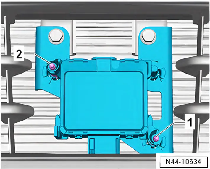
Designation of adjusting screws of adaptive cruise control unit - J428-
- 1 Adjuster screw 1
- 2 Adjuster screw 2