
1.2 TDI CR engine (EA189) · Removing and installing engine · Removing and installing engine
Removing engine
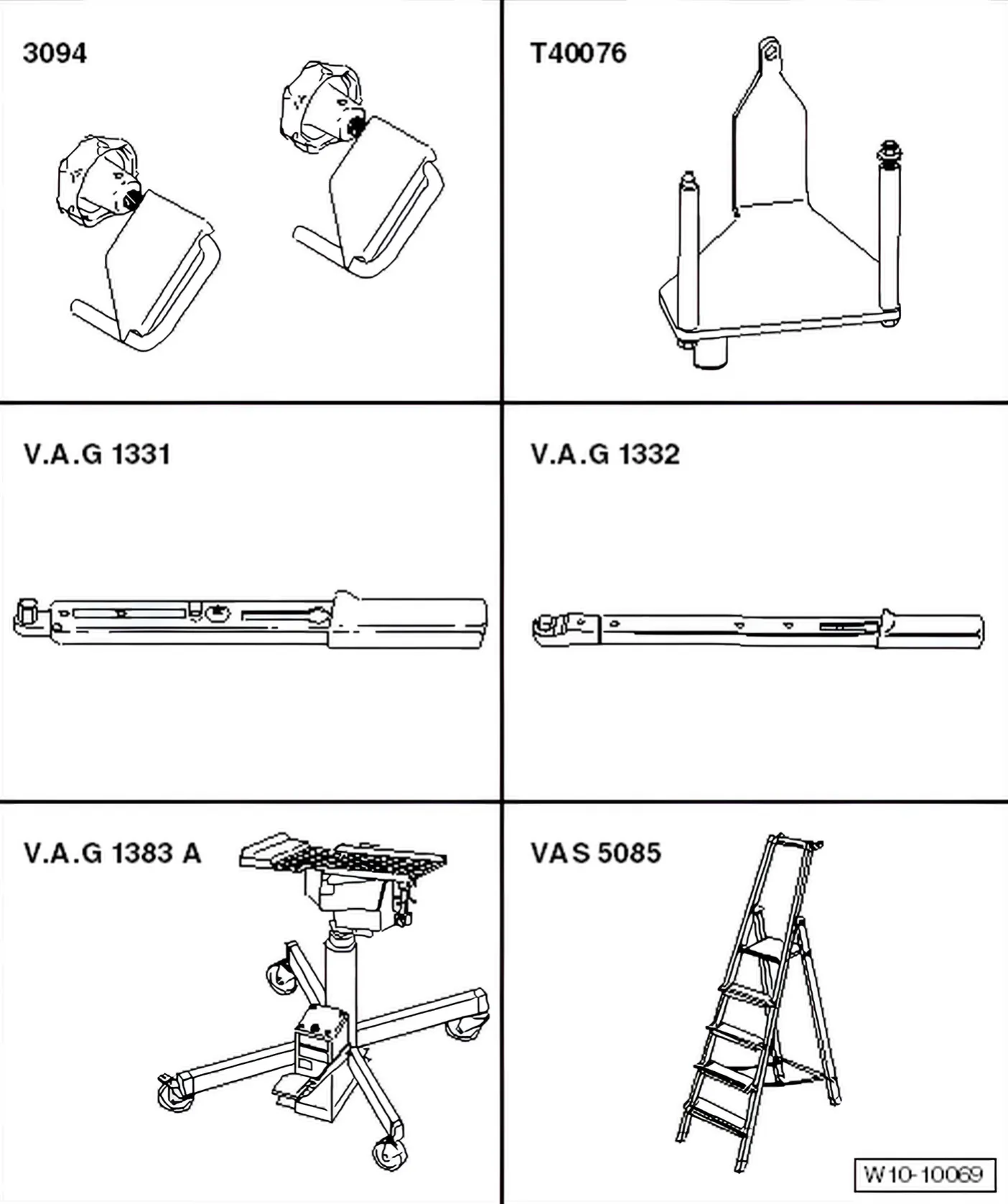
Special tools and workshop equipment required
- Hose clamps to 25 mm - 3094-
- Torque wrench - V.A.G 1331-
- Torque wrench - V.A.G 1332-
- Engine and gearbox jack - V.A.G 1383 A-
- Stepladder - VAS 5085-
- Engine support - T40076-
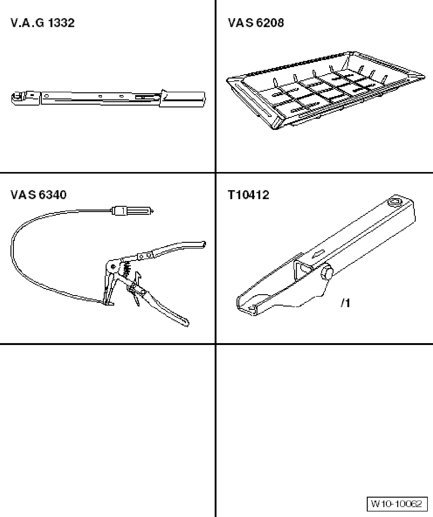
- Torque wrench - V.A.G 1332-
- Drip tray for workshop hoist - VAS 6208-
- Hose clamp pliers - VAS 6340-
- Gearbox support - T10412-
- Grease (vehicles with manual gearbox) - G 000 100-
- Cable tie
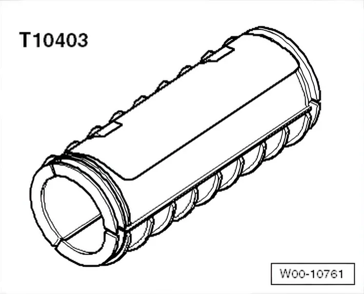
Transportation lock - T10403-
Engine bung set - VAS 6122- (not shown)
»Carry out the following work sequence«
Removing
- Remove engine cover panel ⇒ 3 Engine cover panel.
- With ignition switched off, disconnect battery earth strap. ⇒ Electrical system; Rep. gr. 27; Disconnecting and reconnecting batteries.
- Remove battery and battery tray ⇒ Electrical system; Rep. gr. 27; Removing and installing battery.
- Remove air filter.
- Drain coolant ⇒ 19 – Cooling.
Vehicles with air conditioning system
- Extract refrigerant ⇒ Rep. gr. 87.
Continued for all vehicles
- Remove lock carrier ⇒ General body repairs, exterior; Rep. gr. 50.
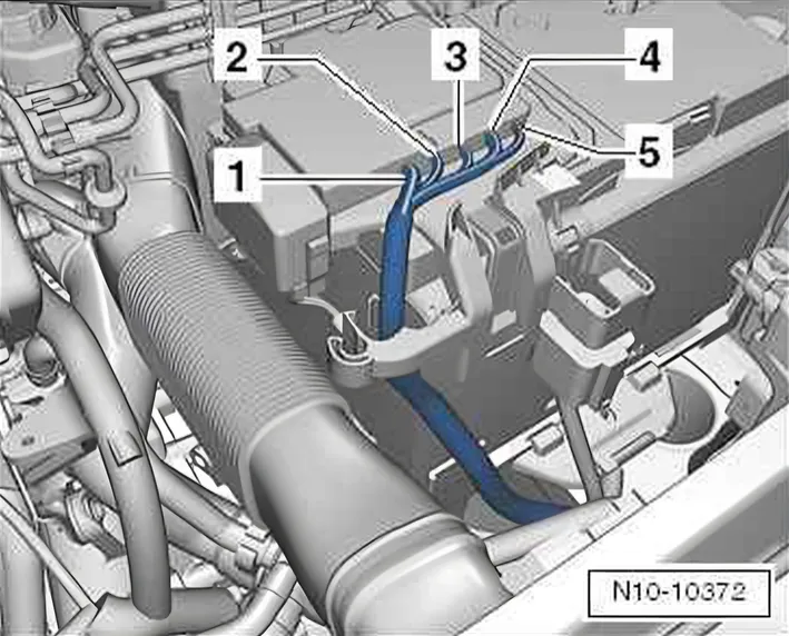
- Unscrew positive cable -1- from battery positive distributor.
- Lay cable down on engine during further work sequence.
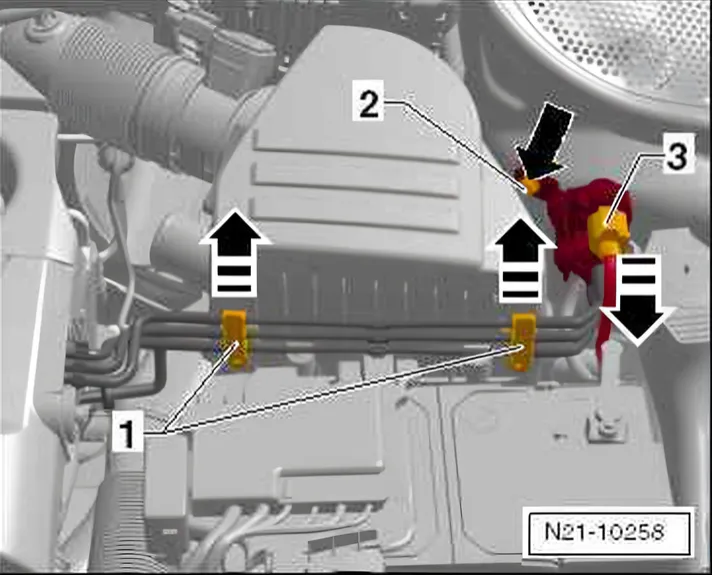
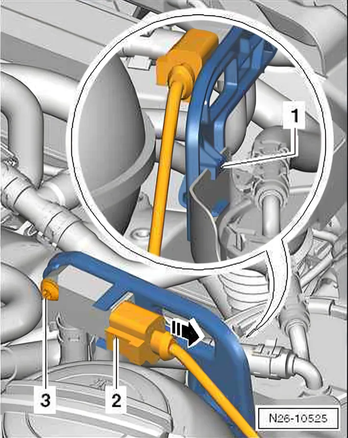
- Remove vacuum hoses with bracket -1- from air filter.
- Remove connector from charge pressure control solenoid valve - N75- -3-.
- Unbolt charge pressure control solenoid valve - N75- with bracket -2-.
- Place charge pressure control solenoid valve - N75- with vacuum lines on engine.
- Remove charge air pipe »hot« side ⇒ 2.3 Fitting charge air system hose connections.
- Remove charge air pipe »cold« side ⇒ 2.3.2 Removing and installing charge air pipe »hot« side.
Vehicles with air conditioning system
- Remove AC compressor ⇒ Rep. gr. 87; Removing and installing air conditioner compressor.
Continued for all vehicles
- Remove starter ⇒ Electrical system; Rep. gr. 27; Removing and installing starter.
- Remove vacuum hose between vacuum pump and brake servo.
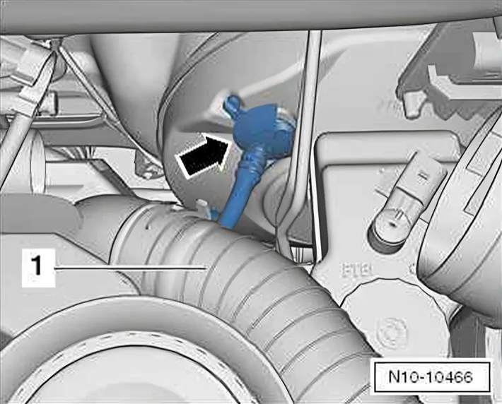
- Detach vacuum line -arrow- on brake servo.
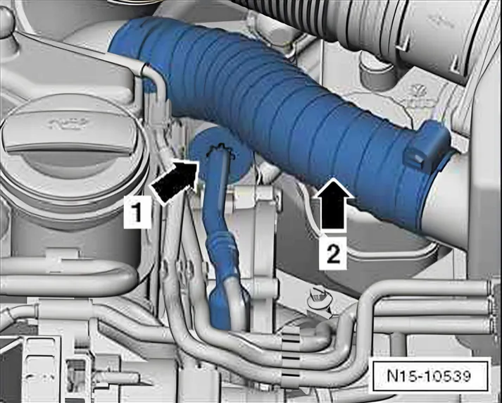
Pre-heater line -arrow 2- is not necessarily installed.
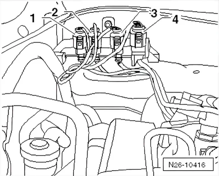
- Disconnect connectors -1 … 4-.
- -1- Exhaust gas temperature sender 1 - G235-
- -2- Exhaust gas temperature sender 3 - G495-
- -3- Exhaust gas temperature sender 4 - G648-
- -4- lambda probe - G39-
- Guide lines out of brackets on plenum chamber bulkhead and on turbocharger.
- Separate electrical connector -2- on pressure differential sender - G505-.
- Unscrew bolt -3- from pressure differential sender - G505- bracket.
- Lay pressure differential sender - G505- with lines down to rear.
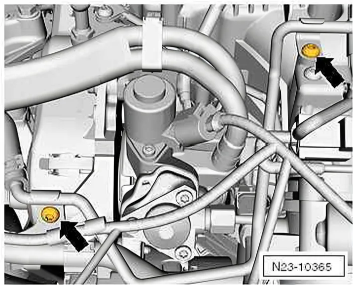
- Unscrew coolant return line bolts -arrows-.
- Lay coolant return line to side.
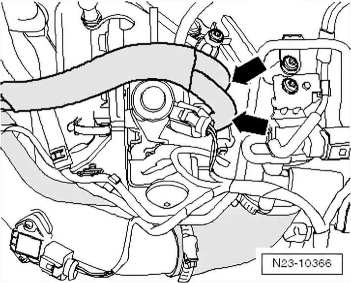
- Remove fuel supply line and return line -arrows- at high-pressure pump.
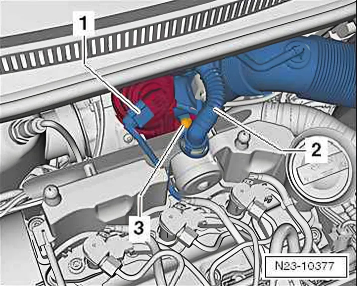
- Disconnect connecting hose -2- from cylinder head cover.
- Unscrew bolt -3- (attached), turn intake hose clockwise out of its bracket and remove.
- Remove engine control unit from its bracket ⇒ 9 Engine control unit.
- Release engine wiring harness connector from engine control unit and remove.
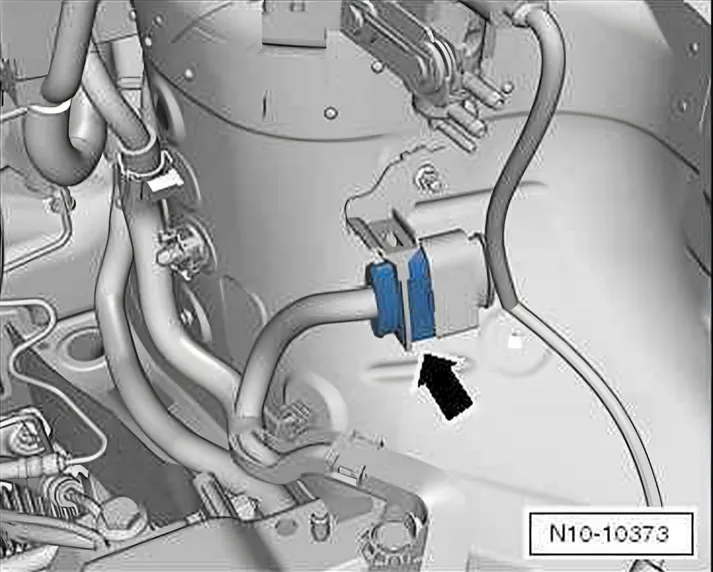
- Disconnect connector -arrow-.
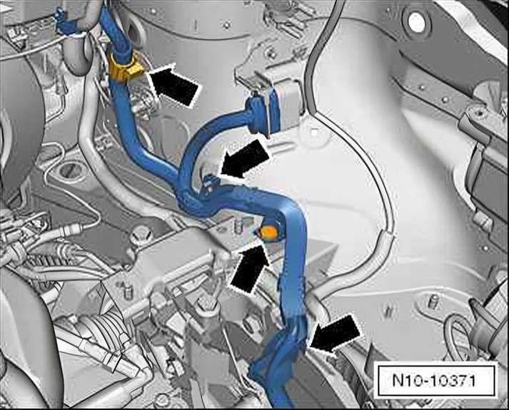
- Carefully loosen engine wiring harness at its fastening points -arrows-.
- Place engine wiring harness on engine.
- Separate all remaining connectors to engine.
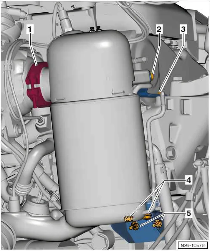
- Loosen particulate filter.
| 1) | Remove securing clamp between particulate filter and turbocharger |
|---|---|
| 2) | Unscrew bolts -2 … 3- |
| 3) | Loosen bolt -4- |
| 4) | Unscrew nuts -5- |
- Push particulate filter aside and secure on plenum chamber bulkhead by suitable means.
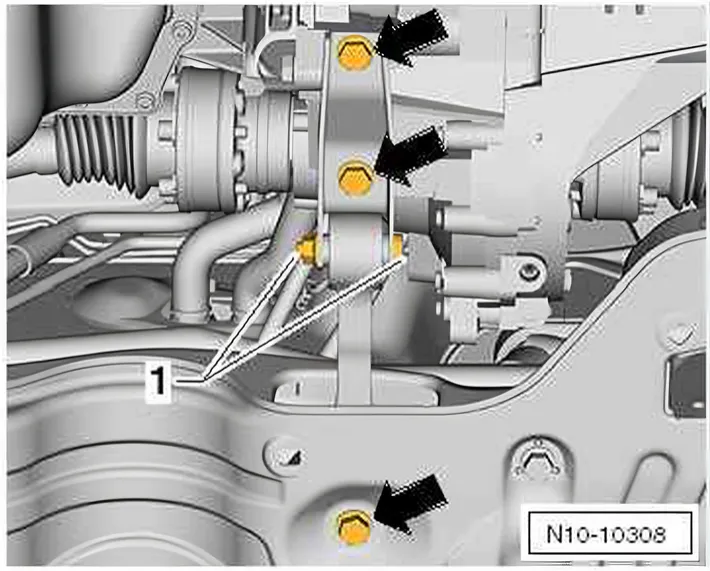
- Unscrew securing bolts -arrows- for pendulum support.
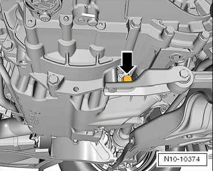
- Unscrew bolt -2-.
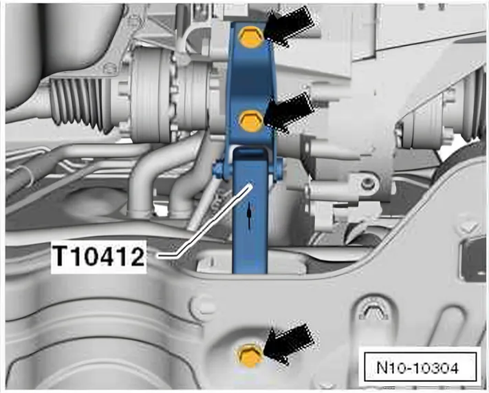
- Install gearbox support - T10412-.
The -arrow- on gearbox support points forwards.
- Tighten securing bolts -arrows- hand tight.
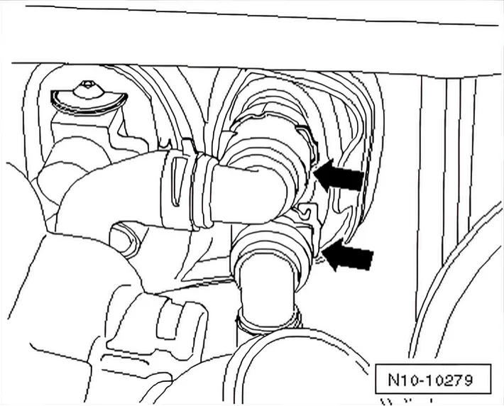
- Disconnect quick-release couplings for heat exchanger -arrows- on plenum chamber bulkhead.
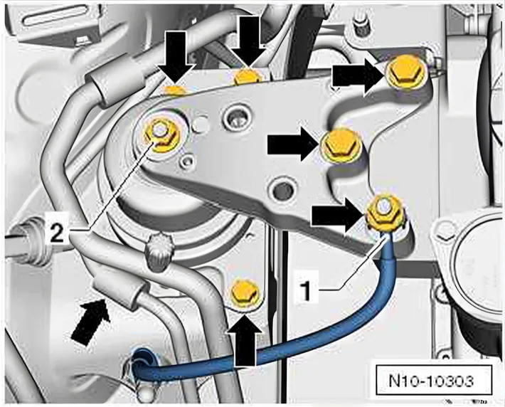
- Unscrew bolts -arrows- on engine mounting approx. 2 turns.
- Seal open lines and unions with clean plugs from engine sealing plug set - VAS 6122-.
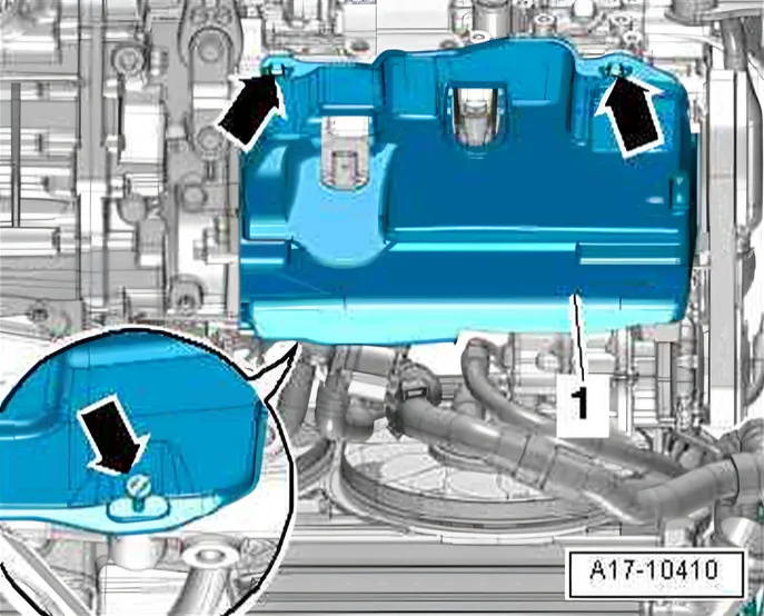
- Open fasteners -arrows- and remove noise insulation -1- for sump.
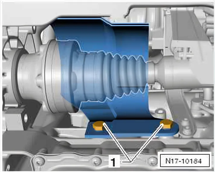
- Remove heat shield for right drive shaft -1-.
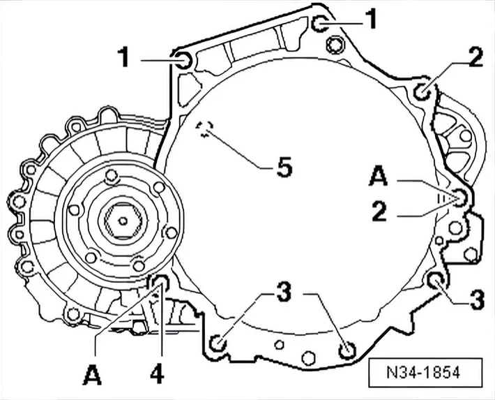
- Unscrew all remaining securing bolts for engine to gearbox.
-5- Small cover plate for flywheel
Item -A-: dowel sleeves for centring
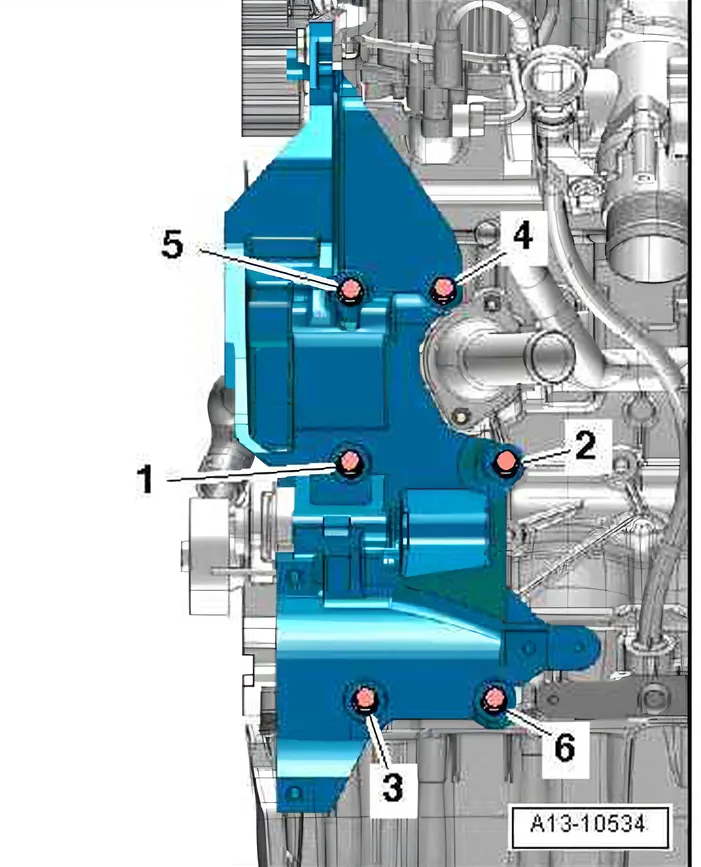
- Unscrew bolt -6-.
- During further procedure, engine bracket - T40076- is secured with a longer bolt -6-.
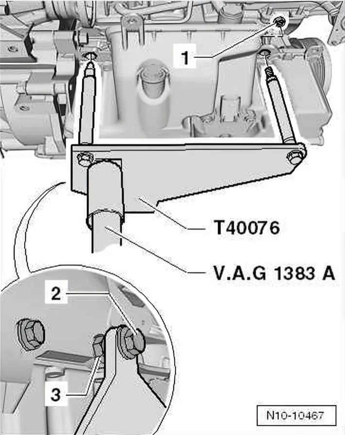
- Screw engine support - T40076- with nut -1- to cylinder block to approx. 20 Nm.
- Fit M12 nut -3- between engine bracket - T40076- and cylinder block.
- Secure engine bracket - T40076- with M10 × 50 nut -2- on cylinder block.
- Fit engine and gearbox jack - V.A.G 1383 A- to engine support - T40076-.
- Insert engine bracket - T40076- in engine and gearbox jack - V.A.G 1383/A-.
- Raise engine/gearbox assembly slightly.
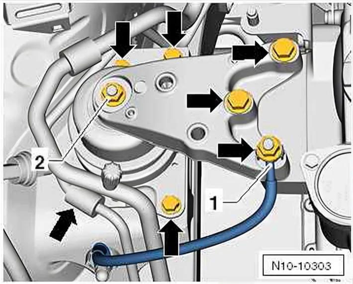
- Completely unscrew securing bolts -arrows- for engine mounting.
- Remove entire engine mounting upwards.
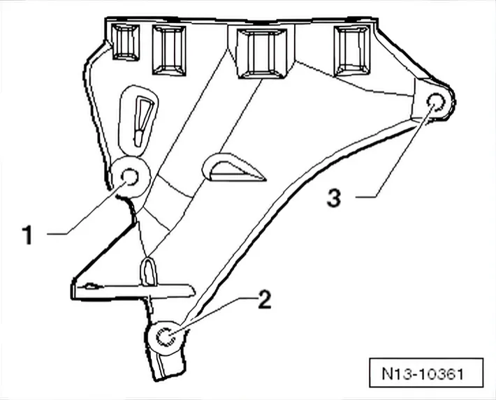
- Remove engine bracket ⇒ 2 Assembly mountings.
- Pull engine out of gearbox.
- Then swivel engine forwards and lower.