
1.4 TSI engine (EA111) · Mixture preparation – injection · Intake manifold
Intake manifold – assembly overview and fastening
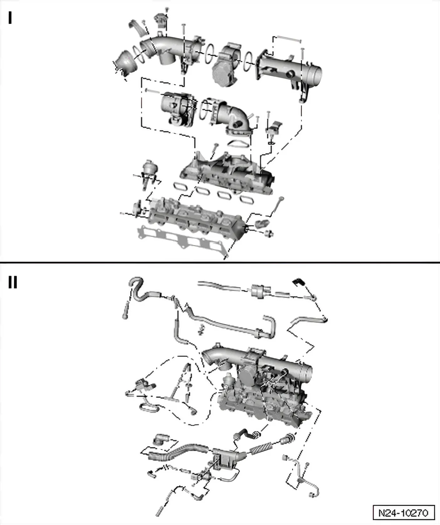
Part I
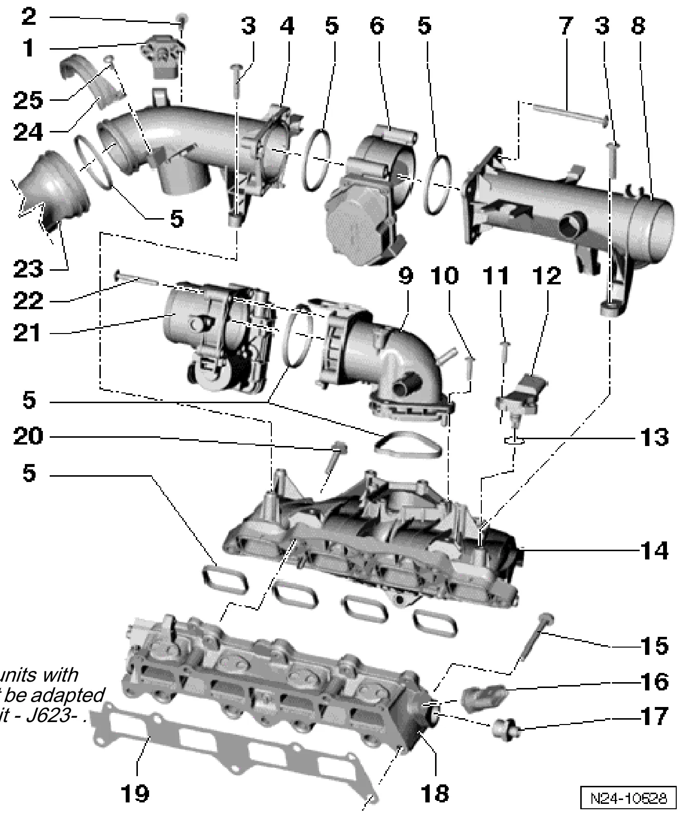
- 1 Intake air temperature sender 3 - G520- with intake manifold pressure sender 3 - G583-
- 2 3 Nm
- 3 7 Nm
- Self-tapping bolt
- The securing bolt may only be tightened using an impact wrench if the wrench speed is max. 500 rpm and a max. specified torque of 7 Nm is set.
- 4 Intake connecting pipe
- 5 Seal
- Renew
- Before installing, lightly coat seal with clean engine oil.
- 6 Regulating flap control unit - J808-
- 7 7 Nm
- Self-tapping bolt
- The securing bolt may only be tightened using an impact wrench if the wrench speed is max. 500 rpm and a max. specified torque of 7 Nm is set.
- 8 Intake connecting pipe
- 9 Intake manifold connection
- 10 7 Nm
- Self-tapping bolt
- The securing bolt may only be tightened using an impact wrench if the wrench speed is max. 500 rpm and a max. specified torque of 7 Nm is set.
- 11 3 Nm
- 12 Intake manifold pressure sender - G71-
- 13 O-ring
- Renew
- 14 Intake manifold
- 15 20 Nm
- 16 Fuel pressure sender - G247-, 22 Nm
- Checking fuel pressure in high-pressure section ⇒ 4.1 Checking fuel pressure sender.
- 17 80 Nm
- 18 Intake manifold lower part
To remove, use holddown device - T10510- ⇒ 2.1 Assembly overview - intake manifold.
Reason: After removing injector, Teflon seal and support washer must be renewed ⇒ 3.3 Renewing seals on injectors.
- To remove and install: using "bracket for bits 5/16""" - V.A.G 1766/2- and Bit - 3320/2- ⇒ 2.1 Assembly overview - intake manifold
- To remove, removing and installing regulating flap control unit - J808-, throttle valve module - J338- and intake manifold ⇒ 2.2 Removing and installing regulating flap control unit - J808- and throttle valve module - J338-.
- 19 Seal
- Renew
- Observe installation position
- 20 20 Nm
- 21 Throttle valve module - J338-
- Removing and installing ⇒ 2.2 Removing and installing regulating flap control unit - J808- and throttle valve module - J338-
- Cleaning ⇒ 2.3 Cleaning throttle valve module - J338-
- If renewed, erase learnt values and adapt engine control unit - J623- ⇒ Vehicle diagnostic tester “Guided functions”.
- 22 7 Nm
- 23 Pressure pipe
- From turbocharger
- 24 Retaining clip
- 25 7 Nm
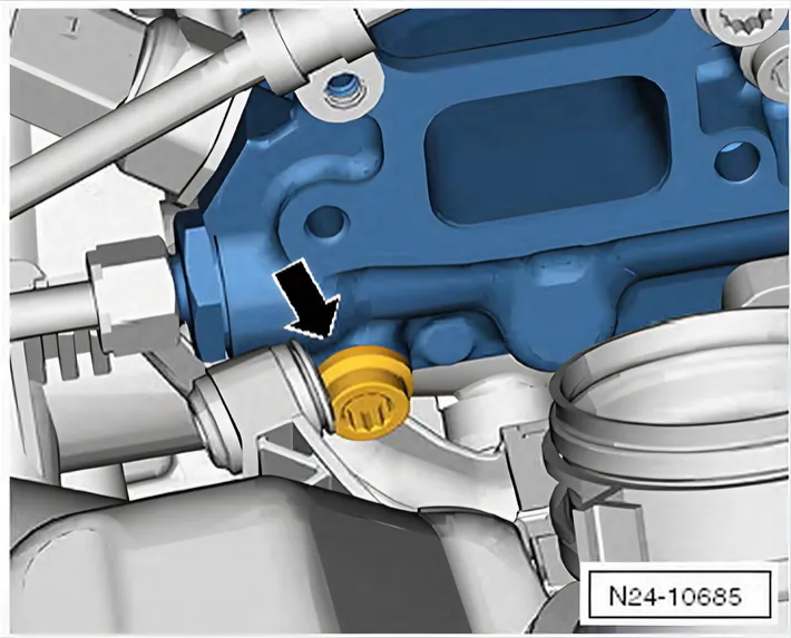
Removing and installing lower part of intake manifold
To remove and install securing bolt -arrow-, use holder for bits with 5/16'' drive - V.A.G 1766/2- and special wrench, long reach - 3320/2-.
Removing
- Insert hold-down device - T10510- in the two holes on cylinder head.
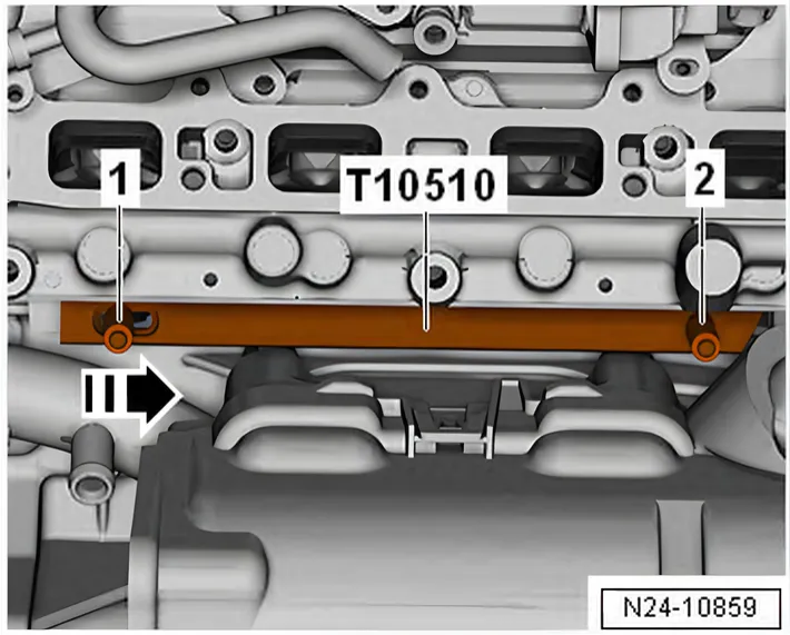
- Push pin -1- in direction of -arrow- until hold-down device is securely seated on injectors.
- Tighten knurled nuts -1- and -2- hand-tight.
- Pull lower part of intake manifold evenly off injectors.
Installing
- Fit new gasket on cylinder head.
- Press lower part of intake manifold evenly onto injectors.
- Remove hold-down device - T10510-.
Specified torques ⇒ 2.1 Assembly overview - intake manifold.
Part II
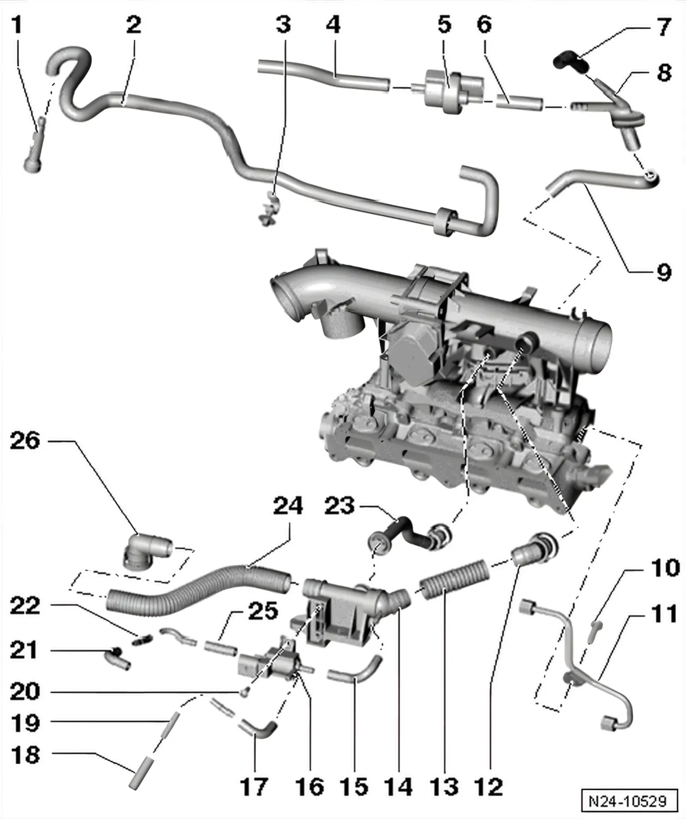
- 1 Union
- For fuel supply.
- 2 Fuel hose
- For fuel supply.
- Low pressure
- To high-pressure pump
- 3 Clamp
- 4 Connection hose
- To activated charcoal filter solenoid valve 1 - N80-
- 5 Activated charcoal filter solenoid valve 1 - N80-
- 6 Connection hose
- 7 To pressure pipe.
- 8 Connecting pipe
- 9 Connection hose
- To intake manifold connection.
- 10 8 Nm
- 11 Fuel line
- High pressure
- Specified torque for union nuts: 18 Nm.
- 12 Union
- To intake connecting pipe.
- 13 Connection hose
- 14 Non-return valve
- For crankcase ventilation.
- Specified torque: 10 Nm
- 15 Connection hose
- 16 Charge pressure control solenoid valve - N75-
- 17 Connection hose
- 18 Connection hose
- To turbocharger
- 19 Union
- 20 5 Nm
- 21 Connection hose
- To turbocharger
- 22 Union
- 23 Union
- For crankcase ventilation.
- 24 Connection hose
- For crankcase ventilation.
- 25 Connection hose
- To charge pressure control solenoid valve - N75-.
- 26 Union
- For crankcase ventilation.
- Connected to valve timing housing.
- Specified torque: 10 Nm