
1.2 TDI CR engine (EA189) · Exhaust system · Exhaust gas recirculation
Cleaning exhaust gas recirculation system
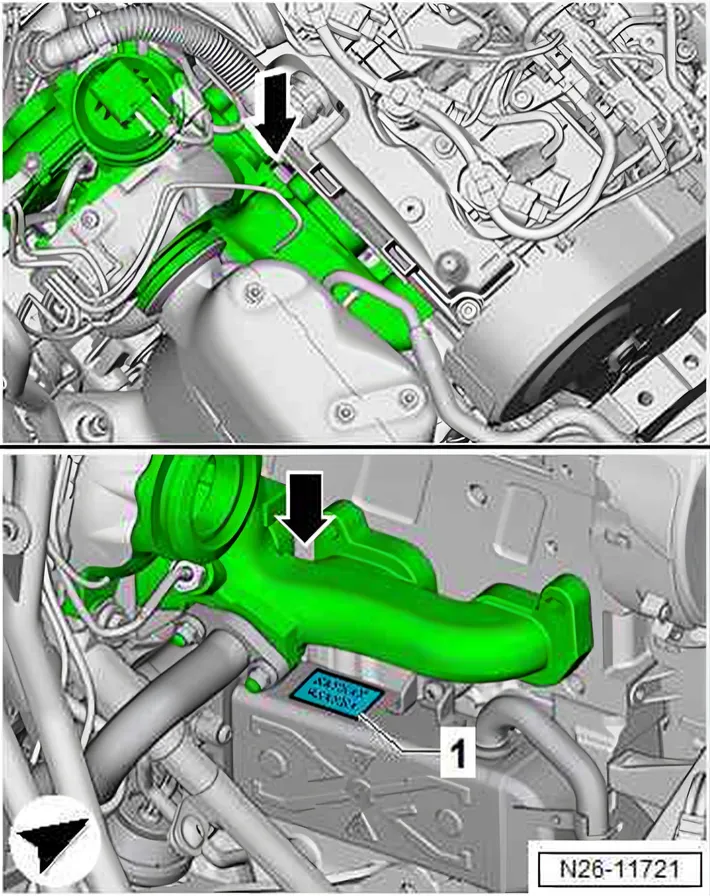
Explanation
With some extreme modes of driving (e.g. short journeys) there is a risk of varnish and coke deposits building up on the inside of the exhaust gas recirculation cooler. In this case, the exhaust emissions warning lamp lights up in the dash panel insert, and the following codes are stored in the event memory:
- P0401 “EGR system flow rate too low”
- P046C “Exhaust gas recirculation sender 1 implausible signal”
- P0405 “Exhaust gas recirculation sender signal too weak”
In most cases, coking or carbonisation can be eliminated by performing the flushing and cleaning procedure described as follows ⇒ 3.5 Cleaning exhaust gas recirculation system.
3.5.1 Initiating cleaning of exhaust gas recirculation system
Special tools and workshop equipment required
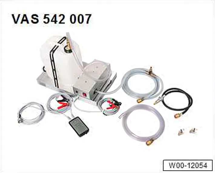
- Cooler flushing system for exhaust gas recirculation - VAS 542 007-
- Remove engine cover panel ⇒ 3 Engine cover panel.
- Open and remove clamp -1-.
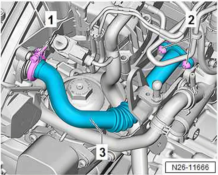
- Unscrew bolts -2-, remove connecting pipe -3- to intake manifold.
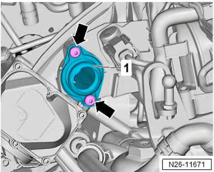
- Unscrew bolts -arrows-, pull out pipe union -1- from intake manifold.
- Fit adapter - VAS 542 007/7- -1- on opening of cylinder head.
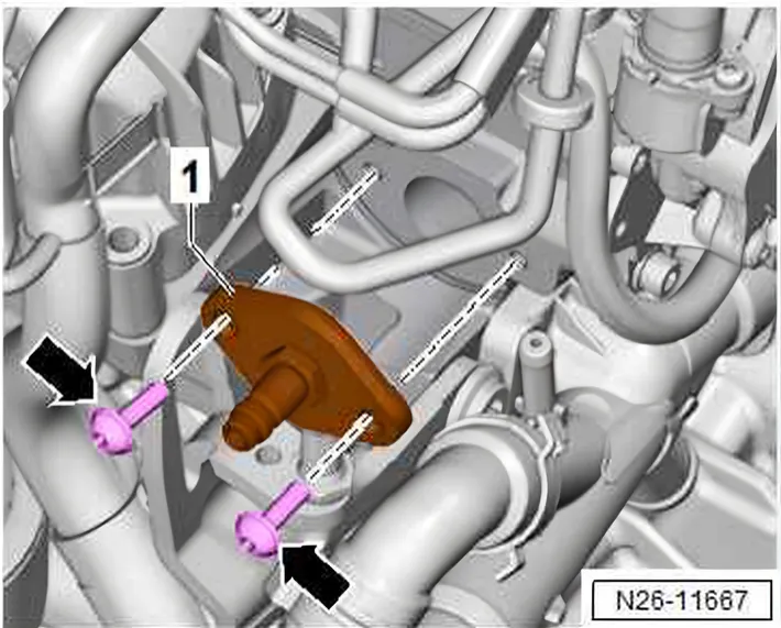
- Screw in original bolts -arrows- of connecting pipe and tighten by hand. Ensure that the seal on the adapter is not crimped.
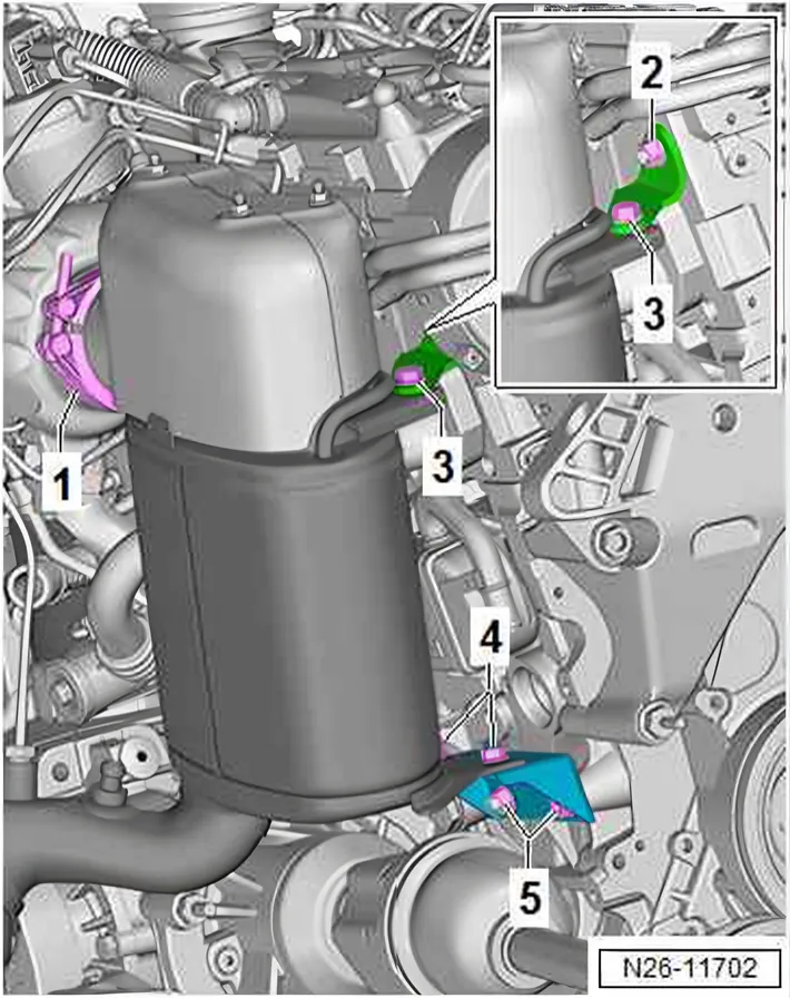
- Unscrew bolt -3-.
- Remove noise insulation ⇒ Rep. gr. 50.
- Unscrew nuts -4- and bolts -5-, remove bracket.
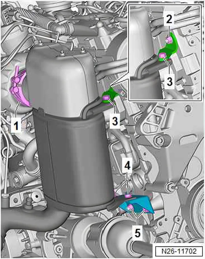
- Open clamp -1- and remove, push particulate filter to one side.
- Unscrew bolts -1- and nuts -2-.
- Remove connecting pipe -3- between exhaust manifold and exhaust gas recirculation cooler.
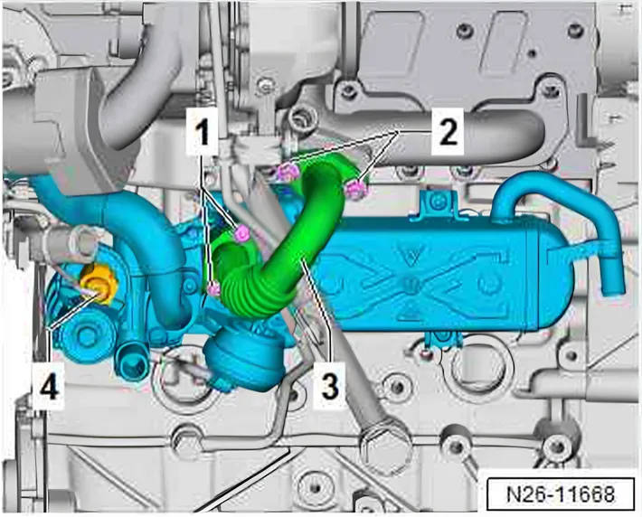
- Release and pull off electrical connector -4- on exhaust gas recirculation valve - N18-.
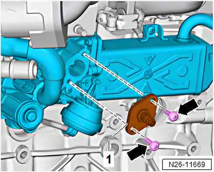
- Fit adapter - VAS 542 007/7- -1- on opening of exhaust gas recirculation cooler.
- Screw in original bolts -arrows- of connecting pipe and tighten by hand. Ensure that the seal on the adapter is not crimped.
- Join supply hose - VAS 542 007/2-2- of cleaning equipment to adapter on exhaust gas recirculation cooler.
- Join return hose - VAS 542 007/2-3- of cleaning equipment to adapter on cylinder head.
- Connect battery charger to vehicle battery.
- Connect terminal clamps of valve positioner - VAS 542 007/6- to vehicle battery.
- Connect terminal clamps of pump - VAS 542 007/3- to vehicle battery.
Prepare cooler flushing system for exhaust gas recirculation - VAS 542 007-
- Fill canister - VAS 542 007/1- with 9 litres of warm (approx. 40°C - 50°C) tap water.
- Pour 1 litre of cleaning solution - D 600 200 A2- into the canister.
- Join suction hose - VAS 542 007/2-1- of pump to connection -1- on canister lid.
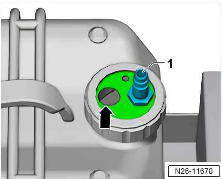
- Insert open end of return hose - VAS 542 007/2-3- into opening -arrow- of canister lid up to approx. half canister height.
- Fit connector of valve adjuster - VAS 542 007/6- on exhaust gas recirculation valve - N18-.
- Switch on valve adjuster - VAS 542 007/6- to open exhaust gas recirculation valve.
- While the cleaning process is running, clean the connecting pipes ⇒ 3.5.1 Initiating cleaning of exhaust gas recirculation system.
- Actuate pump - VAS 542 007/3- as follows:
| Pump - VAS 542 007/3- | Time | Scenario |
|---|---|---|
| Switch on | 25 min. | Clean |
| Switch off | 10 min. | Period for cleaning solution to take effect |
| Switch on | 25 min. | Clean |
| Switch off | --- | End of cleaning process |
- Disconnect intake hose from canister, switch on pump until no more cleaning solution is delivered (system is emptied in doing so).
- Pull out return hose from canister, pay attention to escaping cleaning solution.
- Empty canister, observe country-specific disposal regulations.
- Fill canister with 10 litres of warm (approx. 40°C - 50°C) tap water.
- Join suction hose - VAS 542 007/2-1- of pump to connection on canister lid.
- Feed return hose - VAS 542 007/2-3- into a suitable container (with a capacity of at least 12 litres) and secure in place.
- Switch on pump - VAS 542 007/3- until entire contents of canister have flown through exhaust gas recirculation system.
- Release and pull off supply hose - VAS 542 007/2-2- from adapter on exhaust gas recirculation cooler.
- Connect compressed air adapter - VAS 542 007/5- to adapter on exhaust gas recirculation cooler.
- Insert open end of return hose - VAS 542 007/2-3- into opening -arrow- of canister lid up to approx. half canister height.
- Suction hose - VAS 542 007/2-1- of pump must be joined to connection -1- on canister lid.
- Fit compressed air line to compressed air adapter - VAS 542 007/5-, and completely blow out remaining water from exhaust gas recirculation system.
- Release and pull off compressed air adapter - VAS 542 007/5-.
- Detach adapter from exhaust gas recirculation cooler.
- Pull off connector of valve adjuster - VAS 542 007/6- from exhaust gas recirculation valve - N18-, fit original connector.
- Check effectiveness of cleaning with ⇒ Vehicle diagnostic tester.
- Drive
- 01 - Self-diagnosis compatible systems
| 01 - Diesel direct injection and glow plug system |
| EDC 17 |
- 01 - Engine electronics functions
- 01 - Checking exhaust gas recirculation valve 1 - GX5- after cleaning in accordance with workshop manual
If the result of the test is »Not OK«, the exhaust gas recirculation cooler with integrated exhaust gas recirculation valve - N18- must be renewed ⇒ 3.1 Assembly overview - exhaust gas recirculation.
After cleaning has been successfully conducted:
- Install connecting pipe with new seals and new nuts ⇒ 3 Exhaust gas recirculation.
- Bring particulate filter to installation position with new gasket and new clamp, and secure it ⇒ 2.2.1 Removing and installing particulate filter (LHD).
- Fit noise insulation ⇒ Rep. gr. 50.
- Release and pull off return hose on cylinder head adapter.
- Insert pipe union -1- in intake manifold. Note: opening of union points towards throttle valve module.
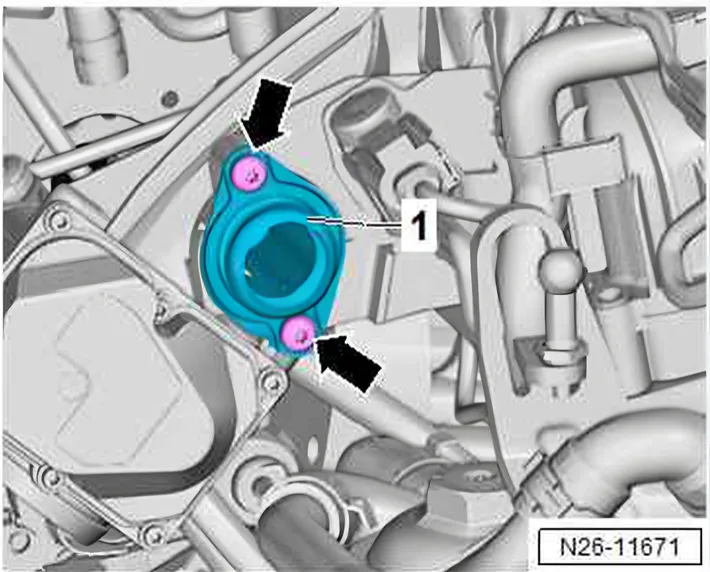
- Screw in bolts -arrows- and tighten to 9 Nm.
- Remove adapter on cylinder head, install connecting pipe with new seal ⇒ 3 Exhaust gas recirculation.
- Fit engine cover panel ⇒ 3 Engine cover panel.
- Carry out road test.
- Therefore, read event memory and erase entries if necessary.
3.5.2 Cleaning connecting pipes and pipe union
Special tools and workshop equipment required
- Ultrasonic cleaning device - VAS 6418-
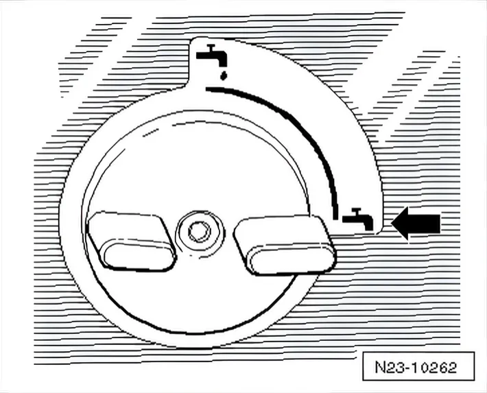
- Close drain tap -arrow- of ultrasonic cleaning unit - VAS 6418- at right-hand side of housing.
- Fill ultrasonic cleaning device - VAS 6418- with 1800 ml of tap water and 200 ml of cleaner - D 600 200 A2-.
- Insert connecting pipes and pipe union. Adjust position of connecting pipes in bath where necessary.
- Switch on cleaning unit by pressing on/off button -C-.
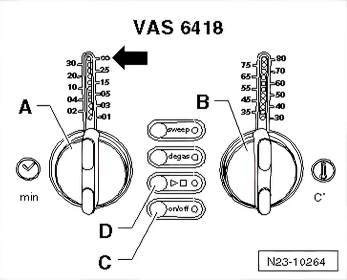
- Turn rotary temperature switch -B- until lamp indicator is at 40° C warm-up temperature
- Set rotary switch for operating period -A- to “10” -arrow-.
- Press and hold ► -D- for longer than 2 seconds and, in doing so, bring equipment into operation.
- Once cleaning is complete, flush connecting pipes and pipe union with clean water and blow out with compressed air.