
1.2 TDI CR engine (EA189) · Turbocharging/supercharging · Turbocharger
Removing and installing turbocharger
Special tools and workshop equipment required
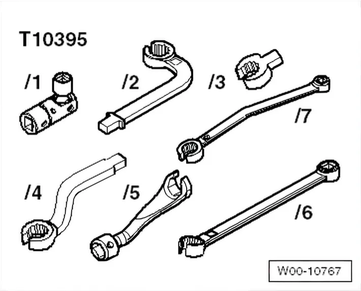
- Tool insert, AF 17 mm - T10395-
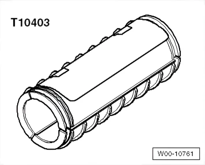
- Transport lock - T10403-
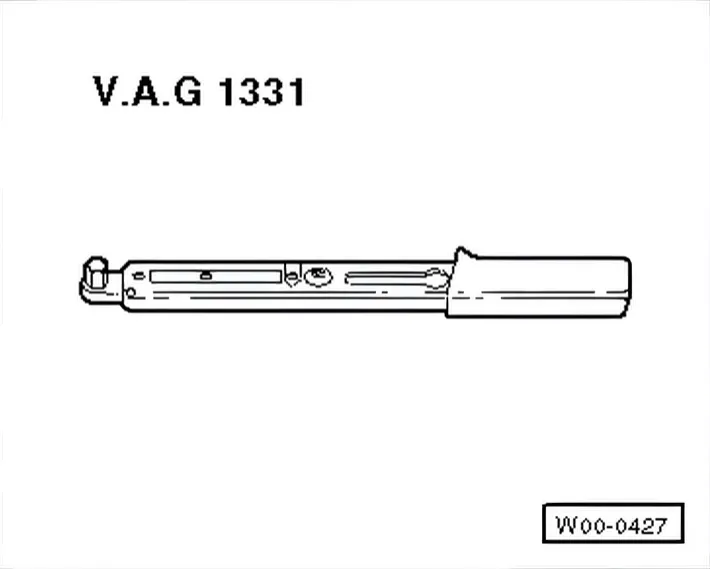
- Torque wrench - V.A.G 1331-
- Used oil collection and extraction unit, e.g. -V.A.G 1782-
If foreign objects are found in the charge air system, the charged air routing must be cleaned and the charge air cooler must be renewed, if necessary.
»Carry out the following work sequence«
Removing
- With ignition switched off, disconnect battery earth strap. ⇒ Electrical system; Rep. gr. 27; Disconnecting and reconnecting batteries.
- Remove engine cover panel ⇒ 3 Engine cover panel.
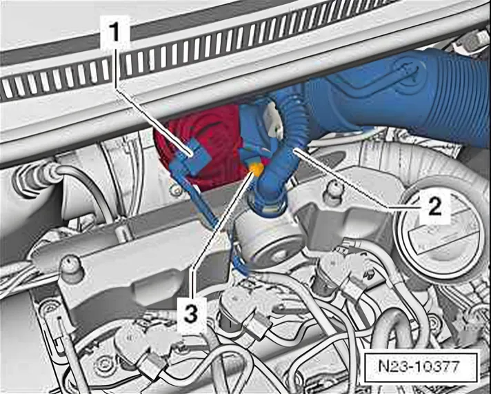
- Pull connector -1- off position sender for charge pressure positioner - G581- on turbocharger.
- Remove connecting hose -2-.
- Unscrew bolt -3- (attached) and screw intake hose clockwise out of its bracket.
- Remove air filter housing with air mass meter and connecting pipe ⇒ 7.1 Assembly overview - air filter.
- Remove plenum chamber bulkhead ⇒ General body repairs; Rep. gr. 50; Body - front; Plenum chamber bulkhead.
- Pull off vacuum hose on turbocharger.
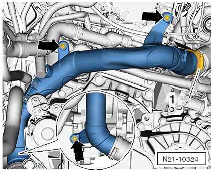
- Loosen upper charge air pipe.
- Loosen clamp -1- on connecting hose to pulsation damper.
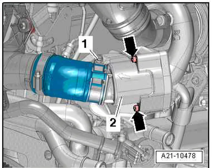
- Remove pulsation damper together with connecting hose.
Loosen particulate filter.
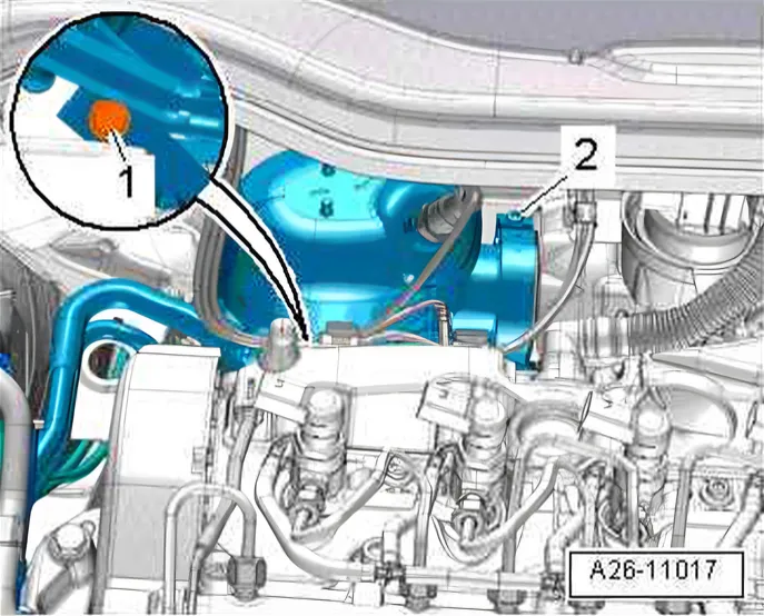
- Remove securing clamp -1- between particulate filter and turbocharger.
- Loosen bolt -2- and remove clamp.
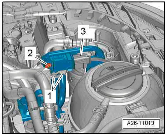
- Disconnect connector -3-.
- Unscrew bolt -2-, remove pressure differential sender - G505-, free hoses -1-.
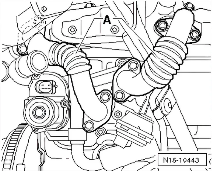
- Remove connecting pipes -A-.
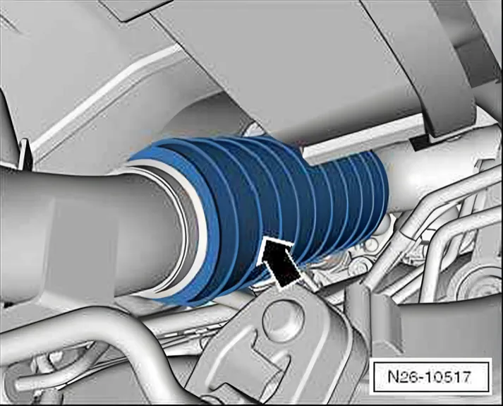
- On flexible joint in front exhaust pipe, fasten the transport lock - T10403- -arrow-.
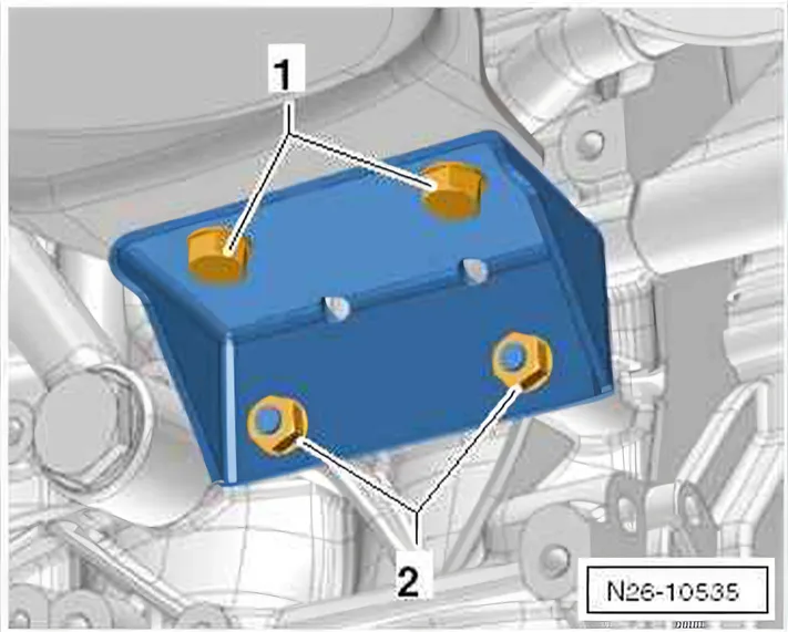
- Unscrew bolts -1- and nuts -2-, remove bracket for particulate filter.
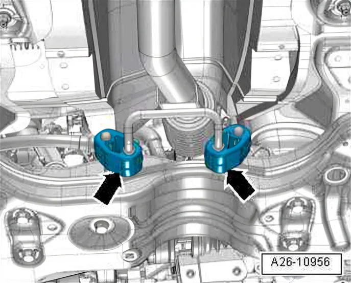
- Pull particulate filter from mountings -arrows-.
- Remove oil supply line and oil return line (turbocharger support) ⇒ 4.1.1 Assembly overview - oil supply line and oil return (turbocharger support).
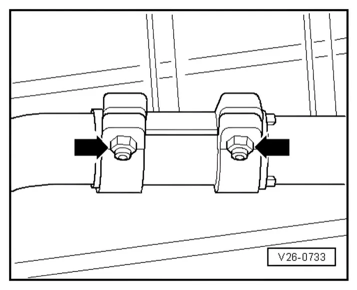
- Loosen securing bolts -arrows- of clamping sleeve, then push down backwards from front exhaust pipe.
- Move particulate filter to side and fix using suitable means.
It must not be bent.
It must therefore be removed.
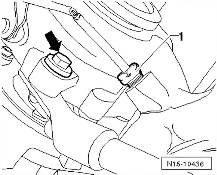
- Remove exhaust temperature sender 1 - G235- -1-.
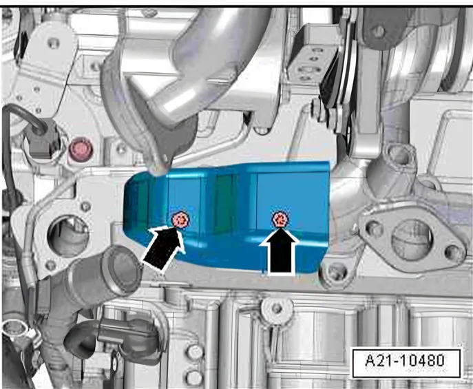
- Unscrew bolts -arrows- and remove heat shield.
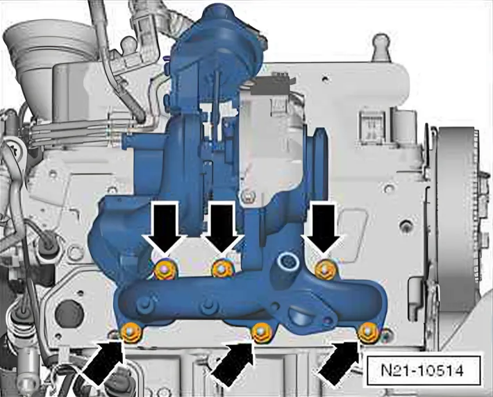
- Unscrew nuts -arrows- and pull turbocharger with exhaust manifold off cylinder head.
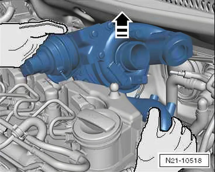
- Carefully remove turbocharger from above in direction of gearbox.
Installing
- Install in reverse order. During this procedure, observe the following:
Specified torques: Turbocharger ⇒ 21 – Turbocharging/supercharging.
Specified torques: Oil supply line and oil return line (turbocharger support) ⇒ 4 Oil circuit.
Specified torques: Connecting pipes ⇒ 3 Exhaust gas recirculation.
- Position connecting hose of charge air pipe before bolting on turbocharger.
- Note installation position of exhaust temperature sender 1 - G235-.
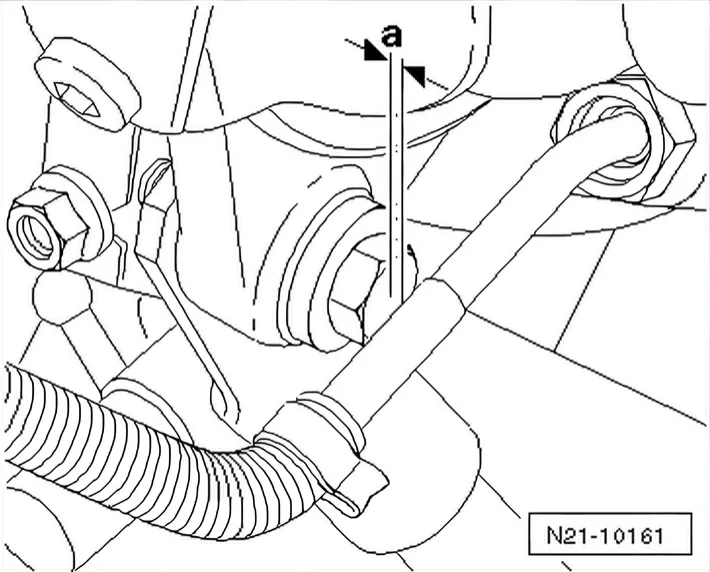
Installation position of exhaust gas temperature sender with angled cable guide
1.2.1 Tightening exhaust gas temperature sender 1 - G235-
Extending the torque wrench - V.A.G 1331- with the spanner from tool set - T10395/7- allows the correct torque of 45 Nm to be achieved.
Lubricate thread of sender using high-temperature paste - G 052 112 A3-.
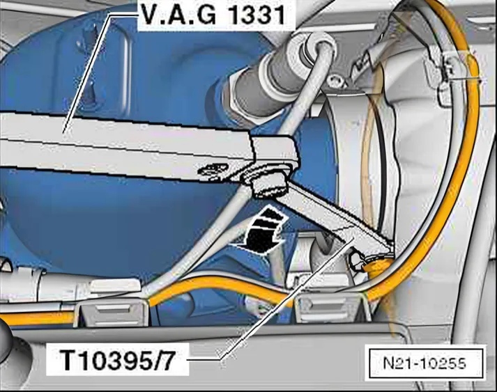
- Screw exhaust temperature sender 1 - G235- in by hand.
- Then apply tightening torque using torque wrench - V.A.G 1331- together with wrench from tool set - T10395/7-.