
Brake systems · Anti-lock brake system · Assembly overview – hydraulic unit, brake booster/brake master cylinder
Bosch 8.2i; 9.0i ABS/EDL/TCS/ESP, LHD vehicles
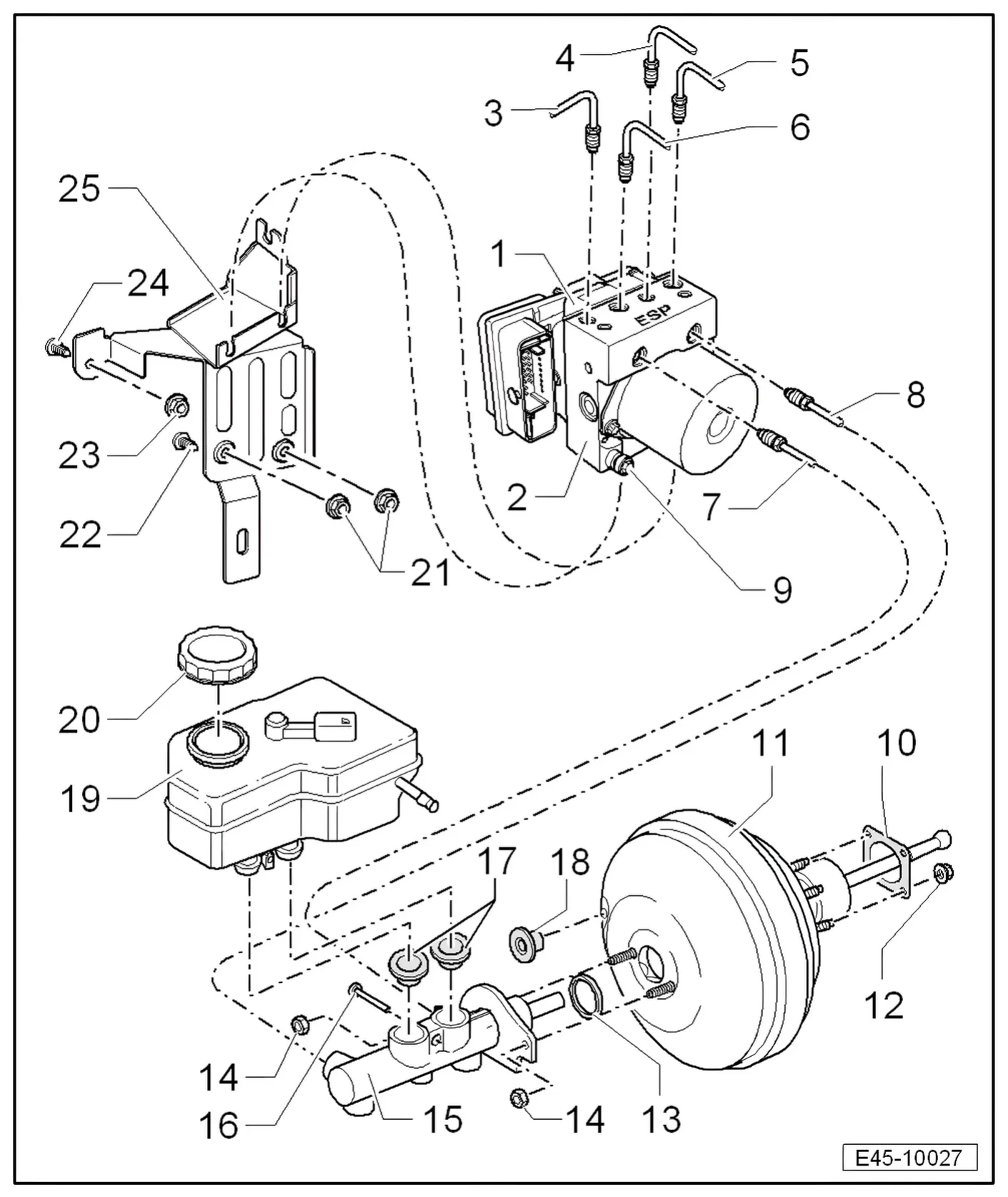
- 1 ABS control unit - J104-
- Removing and installing ABS hydraulic unit - N55- with ABS control unit - J104- ⇒ 6.3.2 Removing control unit and hydraulic unit.
- 2 ABS hydraulic unit - N55-
- ABS return flow pump - V39- and valve block should not be separated from each other
- When replacing the hydraulic unit, always seal the old part with plugs from repair kit - 1H0 698 311 A-.
- Removing and installing ABS hydraulic unit - N55- with ABS control unit - J104- ⇒ 6.3.2 Removing control unit and hydraulic unit.
- 3 Connection for brake line
- From hydraulic unit to front right brake caliper.
- Marked on hydraulic unit with -VR-.
- With thread M10 x 1
- 4 Connection for brake line
- To rear right brake caliper/wheel brake cylinder
- Marked on hydraulic unit with -HR-.
- With thread M10 x 1
- 5 Connection for brake line
- From hydraulic unit to front left brake caliper.
- Marked on hydraulic unit with -VL-.
- With thread M12 x 1
- 6 Connection for brake line
- To rear left brake caliper/wheel brake cylinder
- Marked on hydraulic unit with -HL-.
- With thread M12 x 1
- 7 Connection for brake line
- From primary piston circuit of brake master cylinder to hydraulic unit.
- Marked on hydraulic unit with -HZ1-.
- With thread M12 x 1
- 8 Connection for brake line
- From secondary piston circuit of brake master cylinder to hydraulic unit.
- Marked on hydraulic unit with -HZ2-.
- With thread M12 x 1
- 9 Hexagon nut, 8 Nm
- For 3 rubber damper mountings
- 1 cap nut on side at top; it must be unscrewed to height of stud shoulder, otherwise removal and installation are not possible.
- 2 hexagon nuts with washer at bottom; turn back until rubber dampers can be turned.
- 10 Seal
- For brake booster.
- 11 Brake booster
- Removing and installing ⇒ 7 Removing and installing brake booster.
- 12 Self-locking hexagon nut, 25 Nm
- 13 Sealing ring
- Renew.
- 14 Self-locking hexagon nut, 25 Nm
- 15 Brake master cylinder
- Cannot be repaired. If faulty, renew as a complete unit.
- Removing and installing ⇒ 6 Removing and installing brake master cylinder.
- 16 Securing pin for brake fluid reservoir
- Insert through brake master cylinder
- 17 Sealing plug
- Moisten with brake fluid and press into brake master cylinder.
- 18 Sealing plug
- Connection for vacuum hose.
- 19 Brake fluid reservoir
- 20 Cap
- 21 Self-locking hexagon nut, 20 Nm
- 22 Stud
- Stud welded to body.
- 23 Self-locking hexagon nut, 20 Nm
- 24 Stud
- Stud welded to body.
- 25 Bracket
6.3.1 Connecting brake lines from brake master cylinder to hydraulic unit
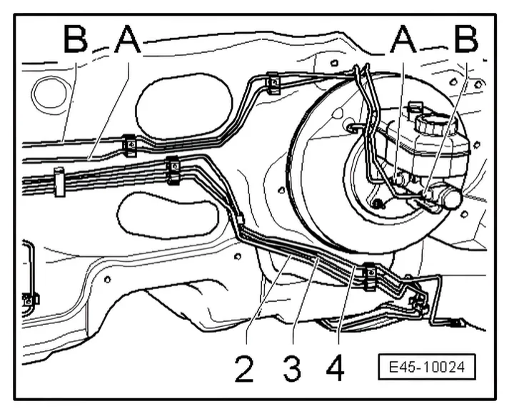
On brake master cylinder:
A - Primary piston circuit of brake master cylinder to hydraulic unit.
B - Secondary piston circuit of brake master cylinder to hydraulic unit.
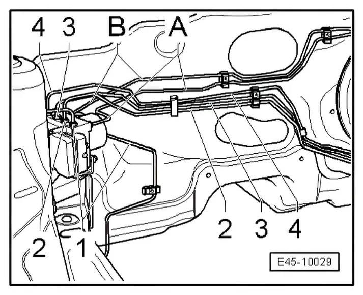
- 2 Hydraulic unit to rear left brake caliper/wheel brake cylinder
- 3 Hydraulic unit to rear right brake caliper/wheel brake cylinder
- 4 From hydraulic unit to front left brake caliper.
On hydraulic unit:
A - From hydraulic unit to primary piston circuit of brake master cylinder
- Marked on hydraulic unit with -HZ1-.
B - From hydraulic unit to secondary piston circuit of brake master cylinder.
- Marked on hydraulic unit with -HZ2-.
- 1 From hydraulic unit to front right brake caliper.
- Marked on hydraulic unit with -VR-.
- 2 Hydraulic unit to rear left brake caliper/wheel brake cylinder
- Marked on hydraulic unit with -HL-.
- 3 Hydraulic unit to rear right brake caliper/wheel brake cylinder
- Marked on hydraulic unit with -HR-.
- 4 From hydraulic unit to front left brake caliper.
- Marked on hydraulic unit with -VL-.
6.3.2 Removing control unit and hydraulic unit

Special tools and workshop equipment required
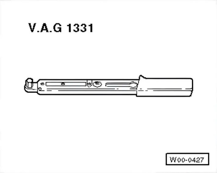
- Torque wrench - V.A.G 1331-
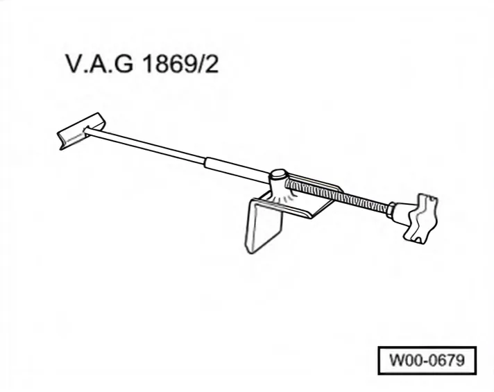
- Brake pedal depressor - V.A.G 1869/2-
Sealing plugs repair kit, Part No. 1H0 698 311 A
Location:
The control unit is bolted to the hydraulic unit and is located on right in the engine compartment.
Removing:
- Read out and note the existing control unit code.
- Note or request radio code on vehicles with coded radio if necessary.
- Disconnect battery ⇒ Electrical system; Rep. gr. 27; Disconnecting and reconnecting battery.
Additional work on following engines:
4-cyl. injection engine, toothed belt drive:
- Pull hose off non-return valve to camshaft housing.
- Remove intake hose and pull air filter housing upwards off pivot pins ⇒ 4-cyl. injection engine, toothed belt drive; Rep. gr. 24.
- .
4-cylinder diesel engine (1.6 l engine, common rail):
- Remove wiper arms ⇒ Electrical system; Rep. gr. 92; Window wiper system; Removing and installing window wiper system.
- Remove plenum chamber cover ⇒ General body repairs, exterior; Rep. gr. 50.
- Pull engine cover panel up out of brackets.
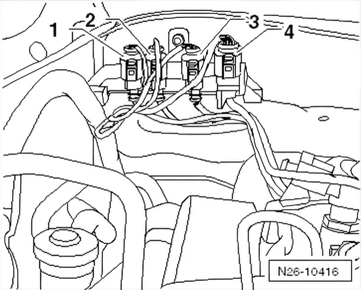
- Disconnect all connectors for electrical wires -1 to 4- to diesel particulate filter and to lambda probe.
- Then remove bracket along with connectors from plenum chamber bulkhead and lay to side.
- Remove intake hose and air filter housing.
- Take engine control unit out of bracket and lay to side.
- Remove bracket for engine control unit.
- Remove insulation from plenum chamber bulkhead.
- Remove plenum chamber bulkhead ⇒ General body repairs, exterior; Rep. gr. 50.
4-cylinder direct injection engines (2.0 l, 4 V, turbocharger, toothed belt drive):
Special tools and workshop equipment required
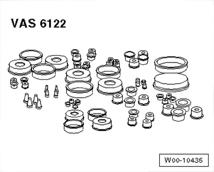
- Set of plugs for engine - VAS 6122-
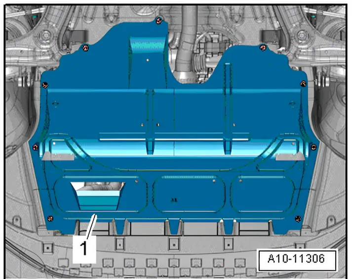
- Remove noise insulation -1- ⇒ General body repairs, exterior; Rep. gr. 66; Noise insulation; Assembly overview - noise insulation.
- Remove air filter housing ⇒ Rep. gr. 24; Air filter; Removing and installing air filter housing.
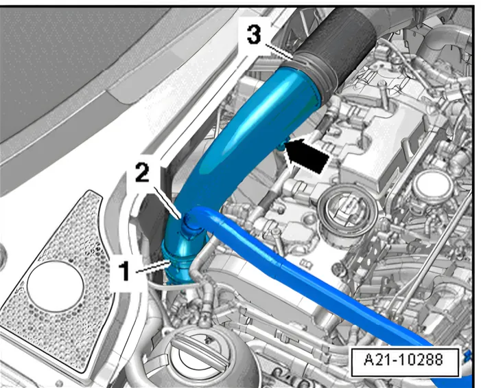
- Unscrew bolt -arrow- for air pipe.
- Loosen hose clip -1-, and place air pipe on engine with hose -2- connected.
- Remove intake hose between air pipe and turbocharger.
- Seal turbocharger with the sealing plug set for engine - VAS 6122/40-.
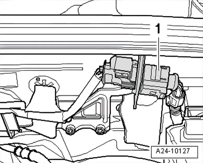
- Disconnect connector -1- for Lambda probe - G39-, and lay it to one side.
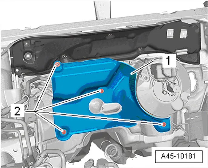
- Detach heat shield -1- in top area and pull it off slightly.
- Evacuate refrigerant circuit, e.g. with air conditioner service station - VAS 6007A- ⇒ Air conditioning systems with refrigerant R134a; Rep. gr. 00; Technical data, before opening refrigerant circuit.
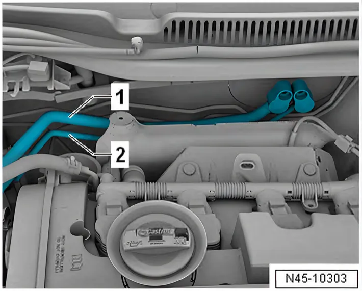
- Unbolt refrigerant lines -1 and 2- on expansion valve ⇒ Air conditioning system; Rep. gr. 87; Refrigerant circuit; System overview - refrigerant circuit.
- Unclip refrigerant lines, and lay them to one side.
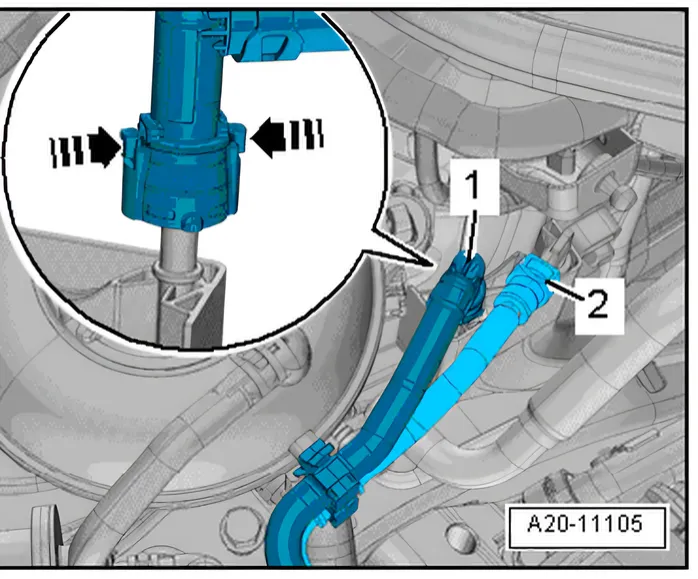
- Disconnect vacuum line -1- and fuel supply line -2-, and unclip them from coolant expansion tank. Separate plug-in connectors ⇒ Rep. gr. 20; Separating plug-in connectors.
- Place the fuel lines to one side.

- Release connector -2- and pull off.
- Undo screws -3-.
- Place coolant expansion tank -1- to one side.
Continuation for all models:
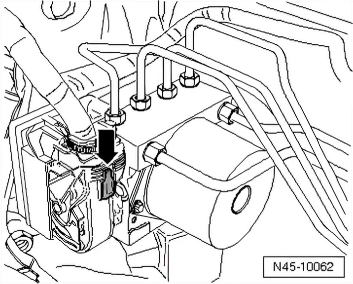
- Press red locking slide -arrow- down.
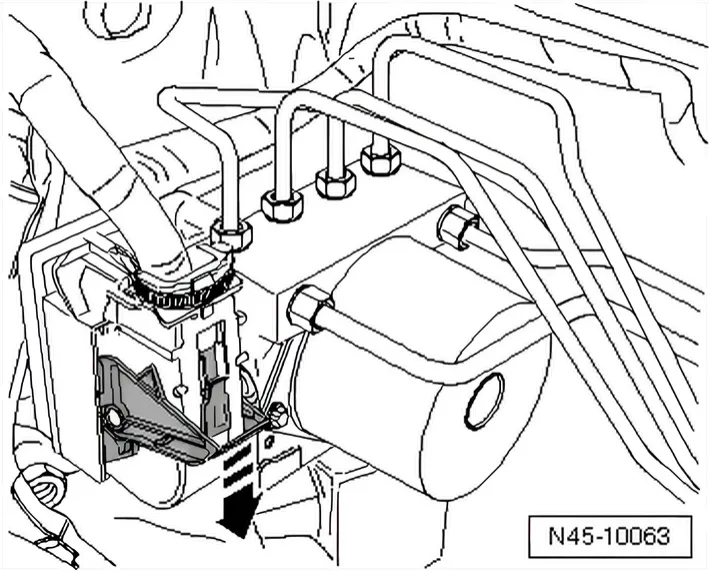
- Release control unit connector -arrow - and pull off forwards.
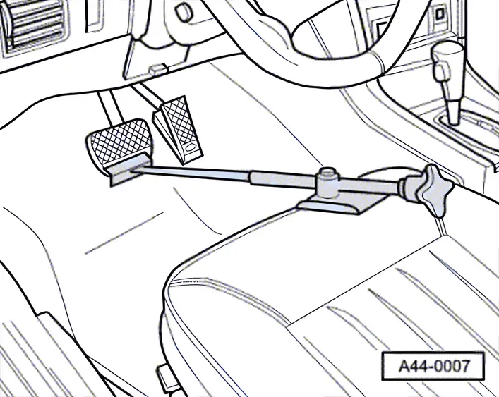
- Apply brake pedal depressor - V.A.G 1869/2-.

- Connect bleed bottle bleed hose -1- to bleed valve of front left brake caliper.
- Open bleed valve.
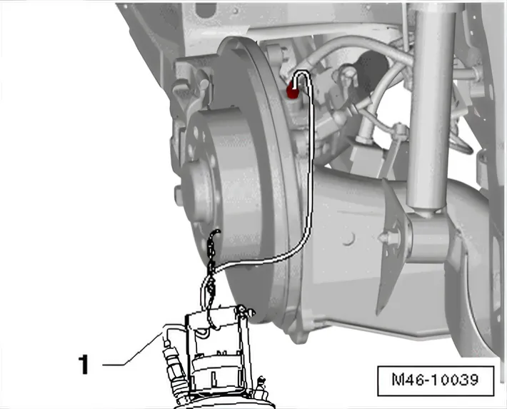
- Connect bleed bottle bleed hose -1- to bleed valve of rear left brake caliper/wheel brake cylinder.
- Open bleed valve.
- Depress brake pedal at least 60 mm using brake pedal depressor - V.A.G 1869/2-.
- Close front left and rear left bleeder valve.
- Do not remove brake pedal depressor - V.A.G 1869/2-.
- Place sufficient lint-free cloths under the control unit and hydraulic unit.
Ensure no brake fluid gets onto contacts.
- Mark brake lines from hydraulic unit -A and B- to brake master cylinder.
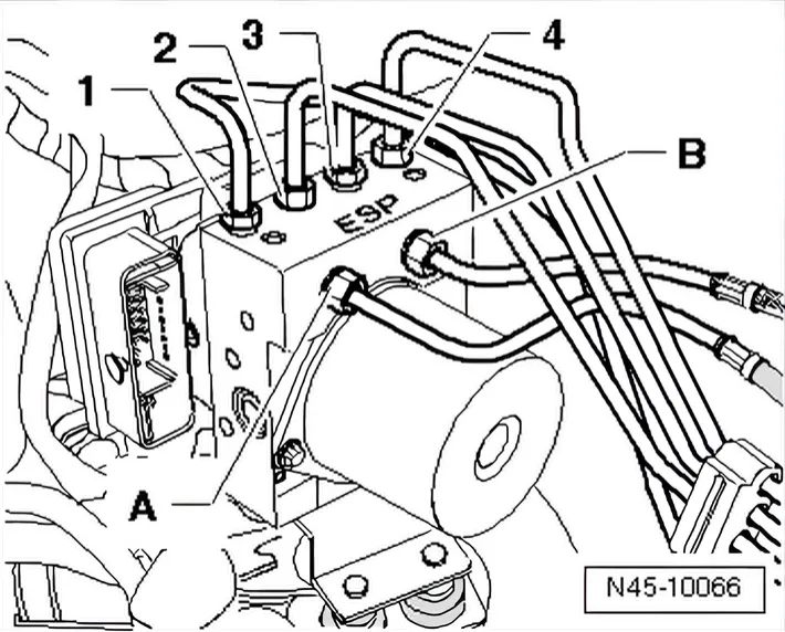
- Then unscrew brake lines from hydraulic unit and from brake master cylinder, unclip from retainers and lay to side.
- Immediately seal brake lines and threaded holes with seal plugs from repair set Part No. 1H0 698 311 A.
- Mark remaining brake lines (to brake calipers) -1 to 4-, unscrew from hydraulic unit and seal.
- Loosen 3 hexagon nuts -1- of rubber damper mountings.

- The cap nut (on side at top) must be unscrewed to height of stud shoulder, otherwise the removal is not possible.
- Pull hydraulic unit with control unit upwards out of bracket.
- If necessary, loosen hexagon nuts of bracket and remove bracket.
6.3.3 Unscrewing control unit from hydraulic unit
Special tools and workshop equipment required
- ESD workplace - VAS 6613-
- If a control unit is defective, the control unit must be disconnected from the hydraulic unit and only the control unit renewed.
- If the hydraulic unit is defective, the hydraulic unit must be renewed together with the control unit.
This electrostatic charge can cause malfunctions if you touch electric components.
- Before working on electric components, touch an earthed object ESD workplace - VAS 6613-. Do not directly touch connector contacts or electronic components.
- Set hydraulic unit with control unit on top on ESD workplace - VAS 6613-.
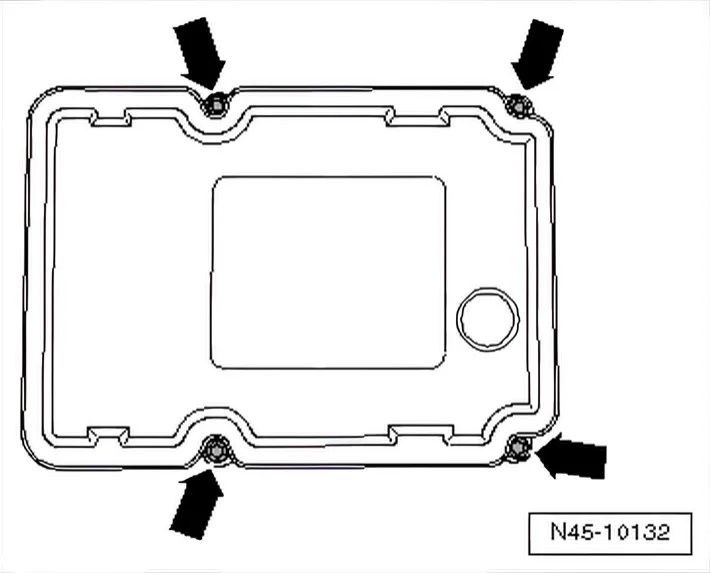
- Remove external Torx screws -arrows- from control unit.
- Taking care not to cant control unit, pull it off hydraulic unit.
- Cover solenoids of control unit with a lint-free cloth.
- Check cleanliness of hydraulic unit sealing surface; clean with methylated spirits and a lint-free cloth if necessary.
Hydraulic unit sealing surface must not be processed with a file, metal scraper, sandpaper or similar.
If hydraulic unit sealing surface is damaged (e.g. scoring, scratches), hydraulic unit must be renewed together with control unit.
After separating control unit and hydraulic unit, use transport protection for contact pins.
6.3.4 Installing new control unit
Special tools and workshop equipment required
- ESD workplace - VAS 6613-
- Torque screwdriver - V.A.G 1624-
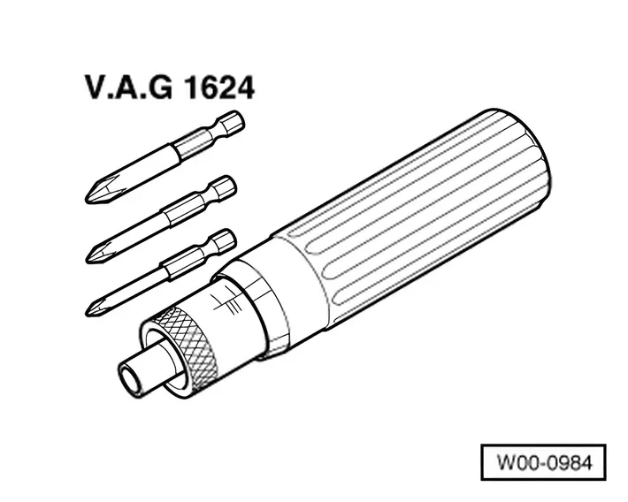
- External Torx bit E6
- Clean surfaces before assembling.
- Without canting it, place control unit onto hydraulic unit.
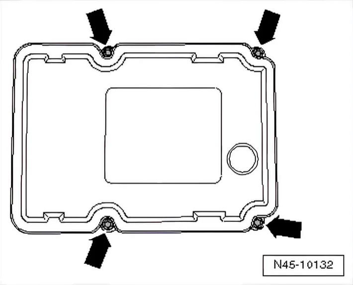
- Tighten hydraulic unit and control unit diagonally in three stages to specified torque with enclosed new Torx bolts.
The hydraulic unit's threads for securing the control unit must not be recut. If the threads are damaged (bolts difficult to turn in by hand or cannot be tightened to the specified torque), hydraulic unit must be renewed.
Specified torque in three stages:
Use new bolts! Stage 1: position and centre control unit; screw in - Torx bolts until Torx bolts contact housing. Stage 2: Seat sealing lugs evenly on all sides and 1.5 to tighten initially.
2 Nm
Stage 3: Final tightening to specified torque. 3 Nm
6.3.5 Installing control unit and hydraulic unit
- Continue installation in reverse order.
- Remove brake pedal depressor - V.A.G 1869/2-.
- Bleed brake system ⇒ 4 Bleeding brake system.
- Code ABS control unit - J104- with ⇒ Vehicle diagnostic tester in “Guided fault finding”.
- Code radio.
Specified torques:
Hexagon nut for rubber damper mounting 8 Nm Hexagon nut to body
20 Nm
Brake lines to ABS unit: Thread M10 x 1
14 Nm
Thread M12 x 1
14 Nm