
SSP 259 EPHS – Electrically Powered Hydraulic Steering
Introduction
Conventional power-assisted steering
The pressure required for the steering servo assistance, is produced by a hydraulic pump.
This pump is driven directly by the vehicle engine, as in the conventional, familiar powerassisted steering system.
In other words, part of the engine power output is required for driving the pump.
At the moment at which the greatest steering servo assistance is required – mainly when parking – engine speed is at its lowest. The pump capacity is designed for such a case. The faster the steering rate, the higher is the pump speed and thus the volume flow. Pump capacity which is not required at higher engine speeds, is dumped via a bypass.
The new steering system
In the new steering system, although the hydraulics likewise assist human steering effort, the hydraulic pump – a gear pump – is driven in this case by an electric motor and is mechanically independent of the vehicle engine. The hydraulic control is of identical design. A new feature is the steering servo assistance based on the steering angle rate and vehicle speed.
A steering angle sensor is additionally integrated for this purpose in the housing of the rotary disc valve (refer to Fig. below), which transmits the steering angle rate to the electronic control. The steering angle information flows along a sensor cable directly to the control unit.
In addition, the vehicle speed is detected in the control unit during the analysis. This information is supplied over the CAN databus.
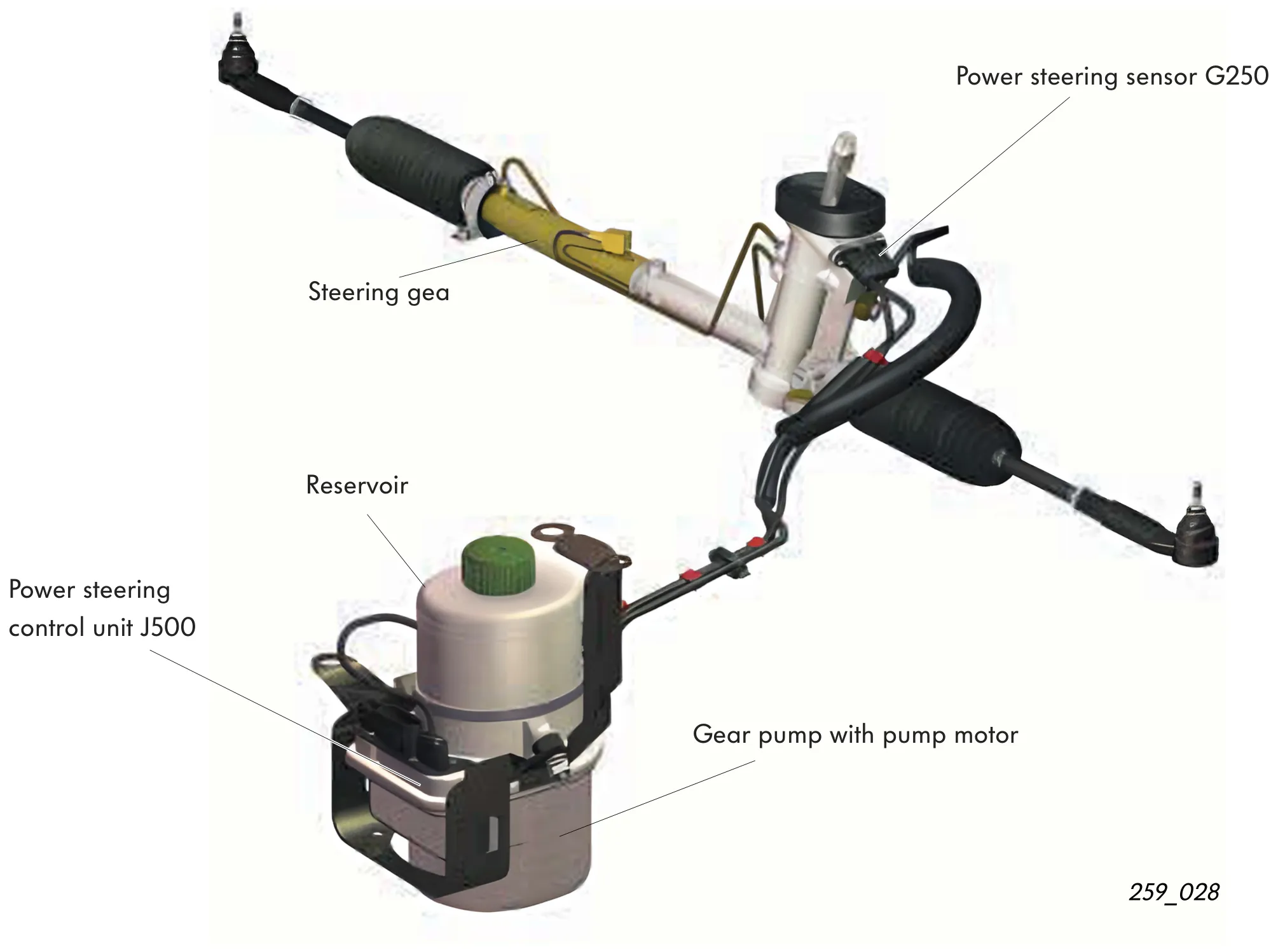
TRW and KOYO steering systems
The steering system fitted to Volkswagen models is supplied by TRW and by KOYO.
The operating principle of both steering systems is identical. The steering systems differ in how they determine the steering angle rate. This is already recognizable from the external shape of the steering angle sensors.
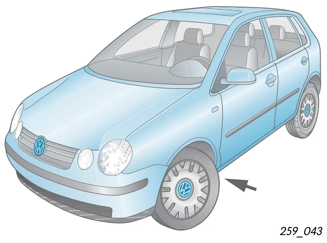
In order to be able to see the power steering sensor in the vehicle, it is necessary to raise the vehicle and to turn the steering to full right lock (see arrow in Fig. on right for direction of viewing).
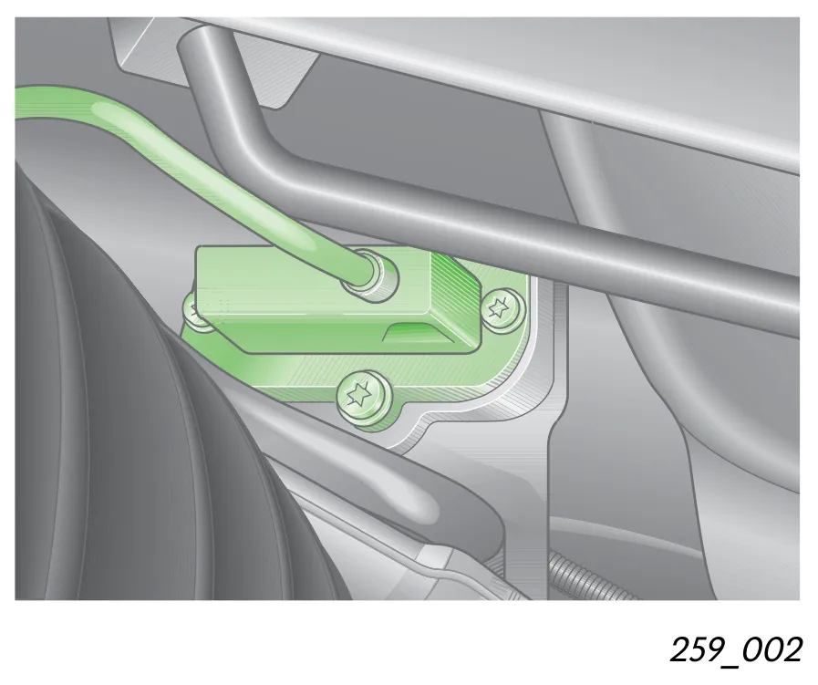
The middle illustration opposite shows a TRW steering fitted in the vehicle. It is recognizable from the power steering sensor which is flat and wide in design (more detailed description from page 13 on).
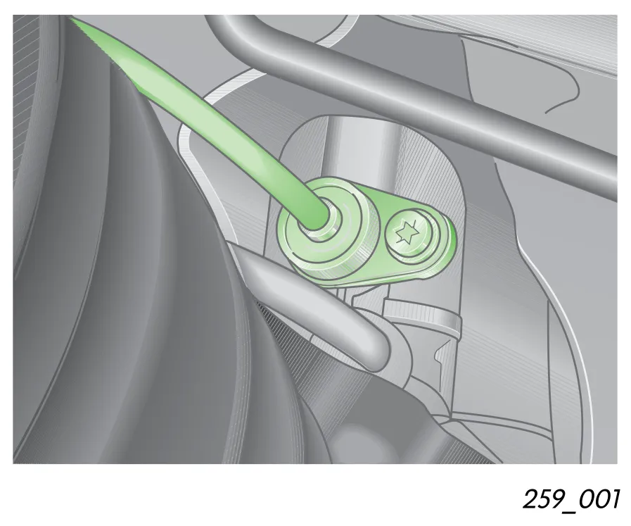
The lower illustration shows a KOYO steering installed in the vehicle. Its power steering sensor is cylindrical in shape (more detailed description from page 15 on).
Overview of the system with its components
The Servotronic warning lamp K92
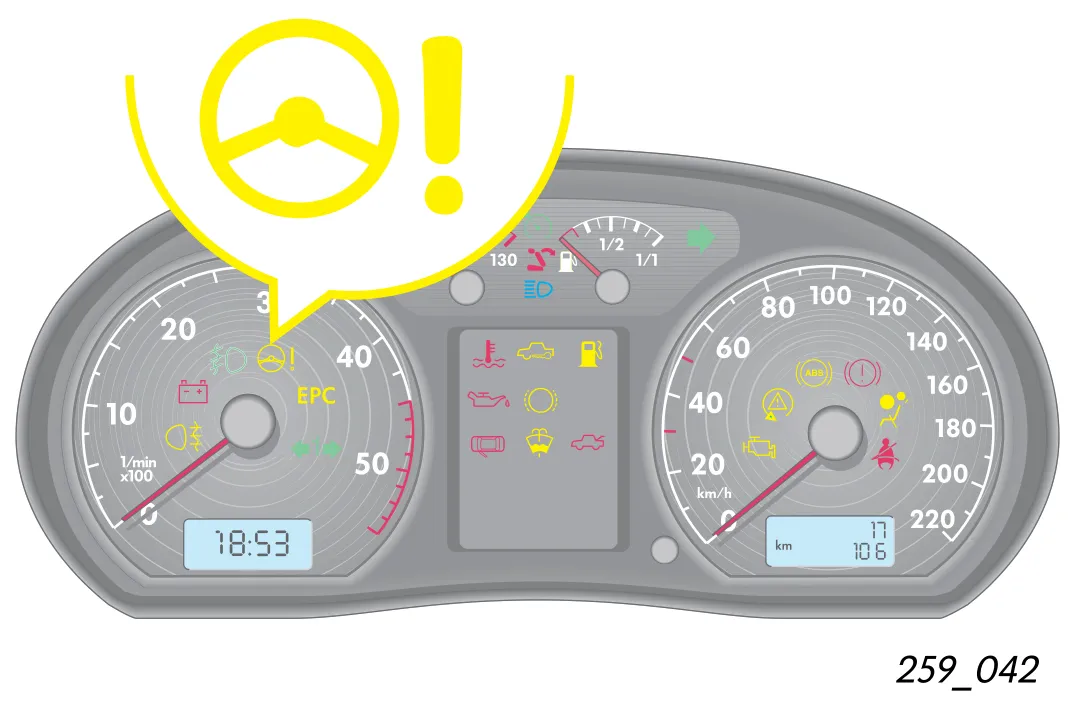
After the ignition is switched on, the Servotronic warning lamp K92 lights up. An internal test cycle takes place during this time.
If the warning lamp does not go out after the engine is started and after the test cycle is completed, faults may be stored in this case.
Power steering sensor G250
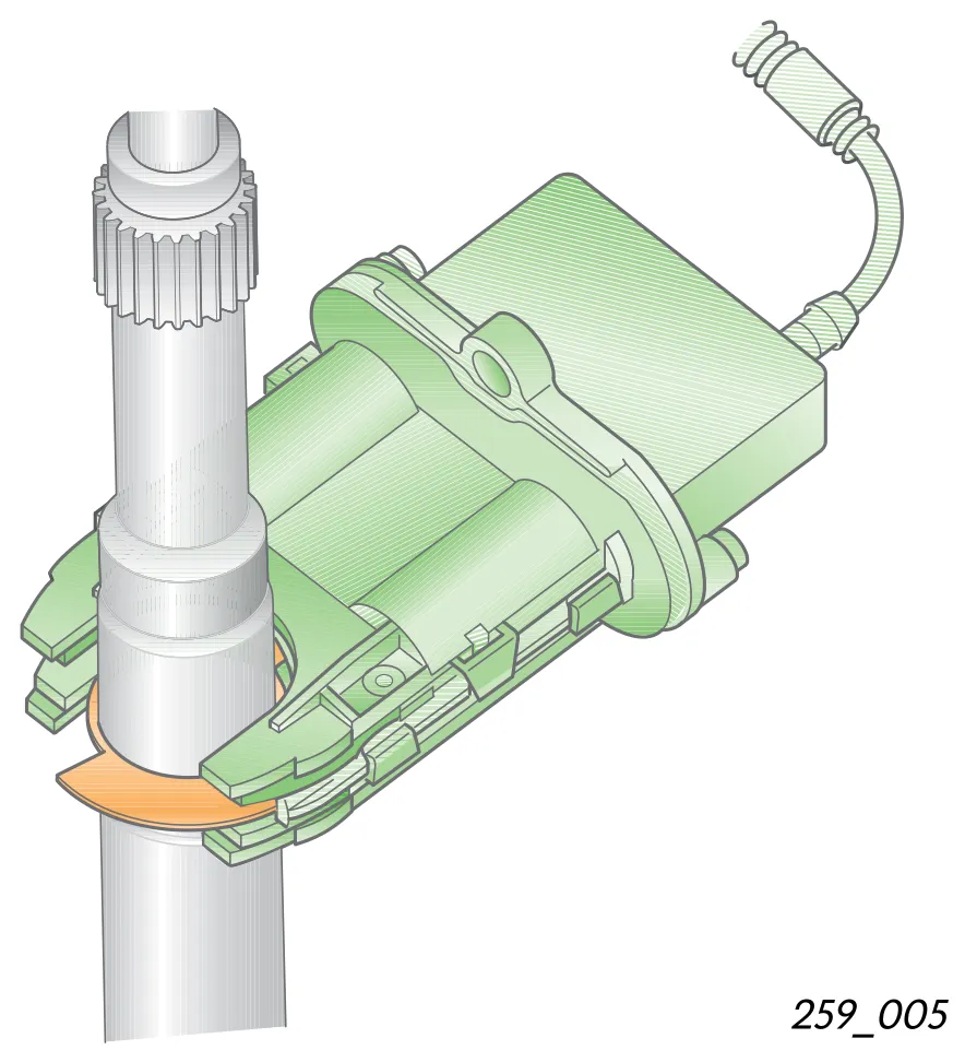
The sensor is integrated in the housing of the rotary disc valve of the power steering gear. It detects the steering angle and calculates the steering angle rate. If the sensor fails, the steering function is nevertheless assured.
The power steering switches over in this case to a programmed emergency running mode. The steering forces required are greater. Malfunctions are stored in the power steering control unit J500.
The illustration opposite shows the power steering sensor of the TRW steering system.
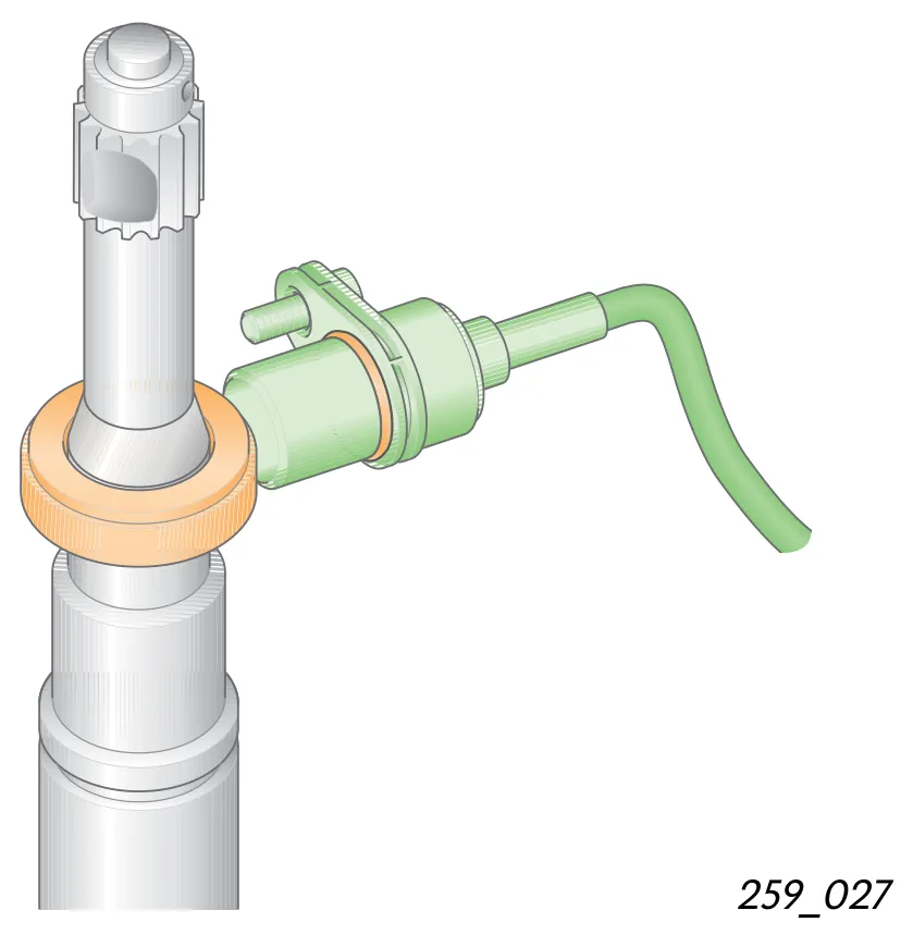
This illustration provides you with a view of the power steering sensor of the KOYO steering system.
The steering angle sender G85
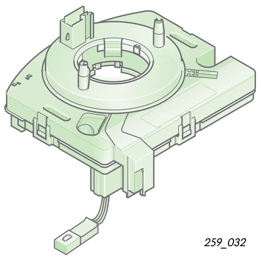
The steering angle sender is located on the steering column between steering column switch and steering wheel. This sensor is used on vehicle models which are available only with the electronic stability programme (ESP). In this case, the power steering sensor G250 is not fitted.
The ABS control unit J104 and the power steering control unit J500 both make use of the signal supplied by the steering angle sender transmitted over the CAN databus, for detecting the angle by which the steering wheel is turned.
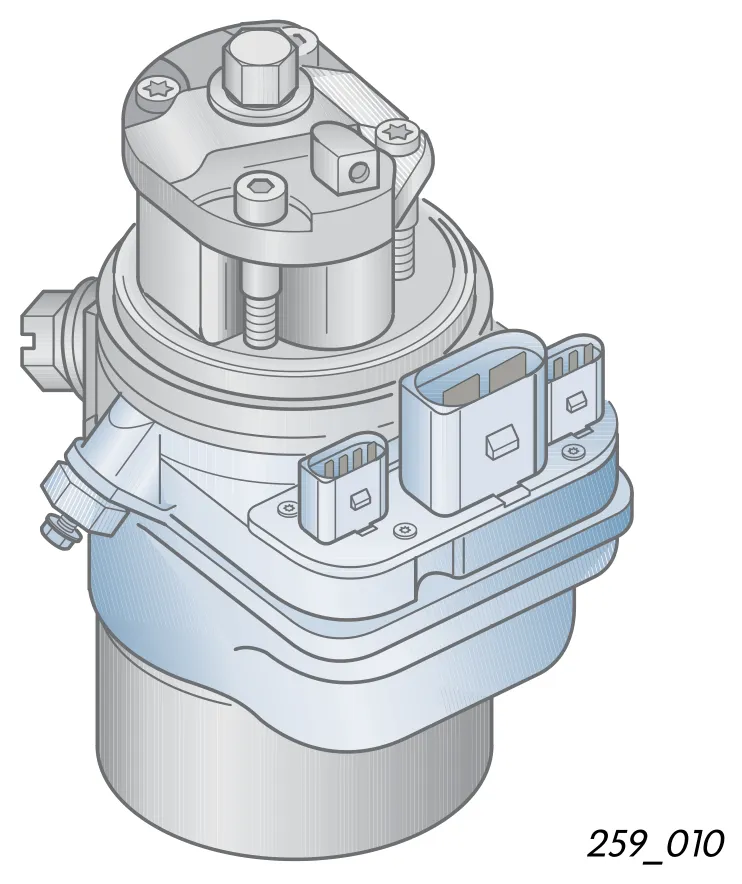
The power steering control unit J500
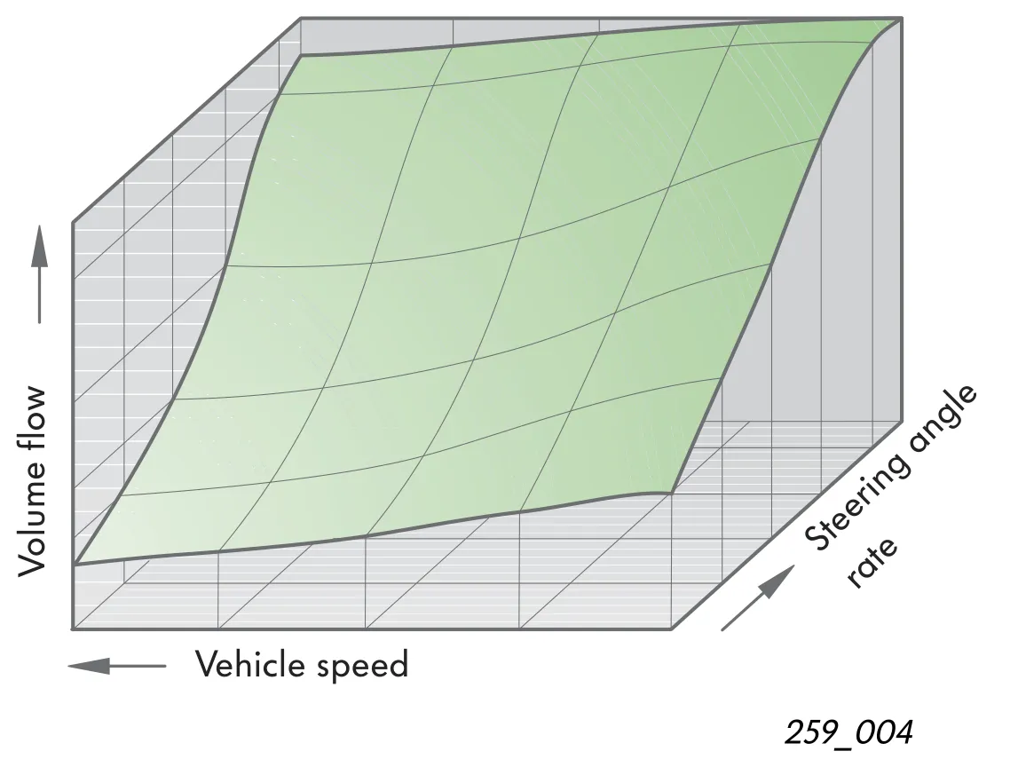
The control unit is integrated in the engine pump assembly. It converts the signals for driving the gear pump in line with the steering angle rate and the vehicle speed. The delivery required at a particular moment is obtained from a map stored in the control unit. The control unit detects and stores faults which occur during operation. A restart protection and temperature protection are integrated in the control unit.