
Sensors
Road speed display
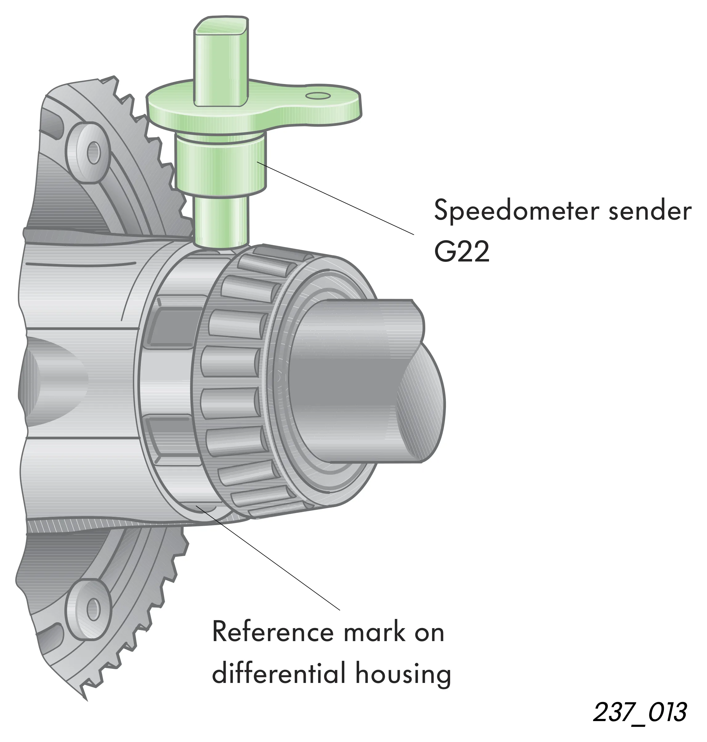
An impulse sender wheel milled in the differential housing generates the signals that speedometer sender G22 requires to determine the actual road speed of the vehicle.
Speedometer sender G22 is inserted in a drill hole in the gearbox housing from the outside.

The sender operates according to the Hall sender principle. The electrical impulses generated by the sender are transmitted to the control unit in the dash panel insert. Here, the signals are conditioned for the actual road speed and mileage display.
Advantage: Ultra-high display accuracy, smooth running, temperature resistant.
Electrical circuit

- D +15 Ignition switch, terminal 15
- G21 Speedometer
- G22 Speedometer sender
- J285 Control unit in dash panel insert
Reversing light switch F4
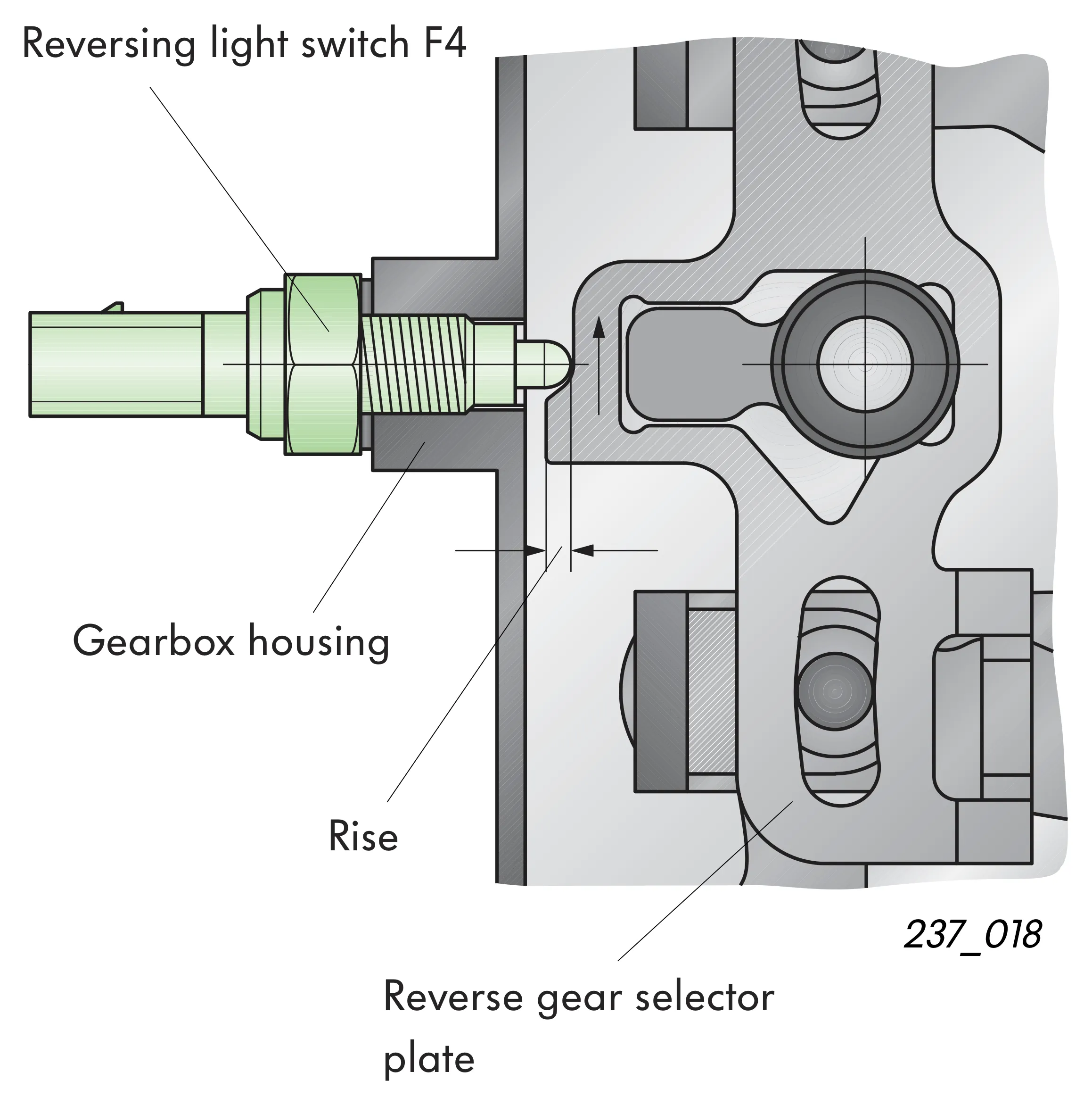
The reversing light switch is screwed into in the gearbox housing at the side.
When reverse is engaged, the switch is actuated by a rise on the reverse gear selector plate.
The electrical circuit for the reversing lights is closed.
Electrical circuit

- D +15 Ignition switch, terminal 15
- F4 Reversing light switch
- M16 Reversing light bulb, left
- M17 Reversing light bulb, right